Instructions for assembling, installing, and using the T-Mech
15T Log Splitter, a powerful tool designed to split logs quickly and efficiently. It includes
safety advice, maintenance tips, and troubleshooting guidance to ensure safe and reliable
operation.
Product Information
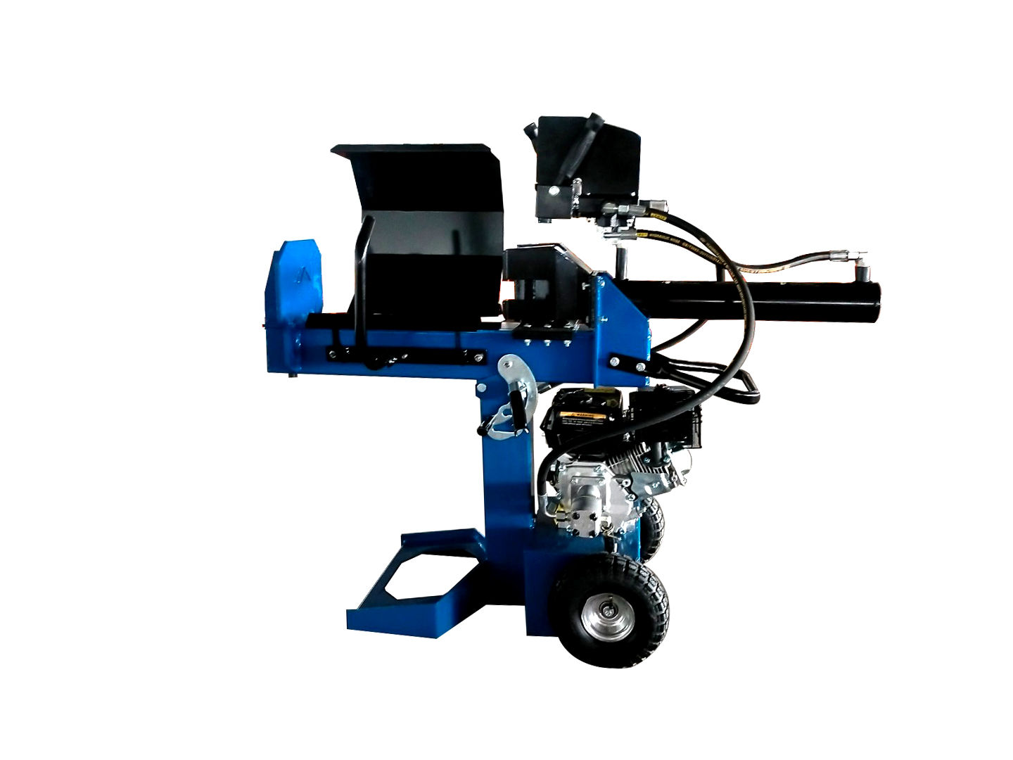
T-Mech 15T Log Splitter & Rain Cover
The T-MECH 15T Vertical Log Splitter is a robust and
efficient machine built to handle demanding wood-splitting tasks with ease. Delivering an
impressive 15 tonnes of splitting force, it features a reliable 7HP gasoline 4-stroke motor and
supports both vertical and horizontal operation for maximum versatility. With a 52cm splitting
length, 2-speed valve, and quick 10-second cycle time, this log splitter is designed for fast,
effective performance. Its durable construction, 10" pneumatic tyres, and compact frame ensure
easy maneuverability and storage, making it ideal for both professional and heavy-duty domestic
use.
SKU
216124
Dimensions
in Vertical Position = L x W x H = 103cm x 47.6cm x 145.6cm
Weight
116kgs
Materials
Q235 Low Carbon Steel, 45# Steel
Product Specifications
Ram Force
12T
Hydraulic Cylinder Size (bore x stroke)
3" x 19"
Gear Pump
2.1 GPM
Maximum Pressure
3500PSI
Cycle Time
16s
Hydraulic Tank Capacity
3.1
Max. Log opening
52cm
Height in horizontal position:
112.4cm
Length in horizontal position:
142.9cm
Width:
47.6cm
GPSR Information
UK
Manufacturer:
Monster Group UK Limited, Monster House
19-23 Alan Farnaby Way,
Industrial Estate Sheriff Hutton,
York
YO60 6PG
Person Responsible:
Rana Harvey, Monster Group UK Limited,
Monster House
19-23 Alan Farnaby Way,
Industrial Estate Sheriff Hutton,
York
YO60 6PG,
England,
+441347878880
EU
Manufacturer:
Monster Group BV,
Van Heemskerckweg 28A & B,
Venlo 5928LL
Netherlands
+441347878880
Person Responsible:
Rana Harvey,
Monster Group BV,
Van Heemskerckweg 28A & B,
Venlo 5928LL,
Netherlands,
+44134787888
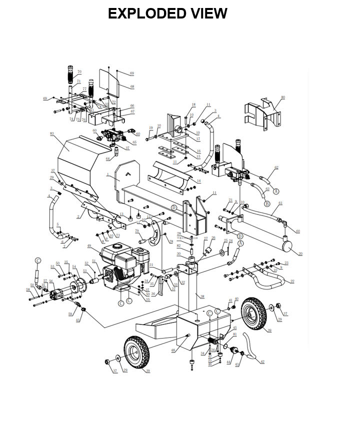
Components
Exploded Diagram
Main Engine Parts
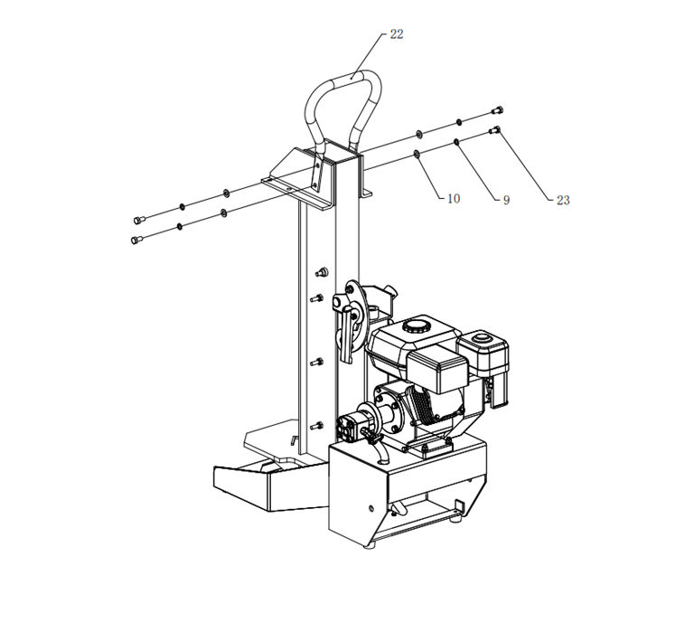
1. Lock & Handle Assembly
1\. Fix the handle (#22) on the end of the beam with bolt (#23), spring washer (#9) and washer
(#10).
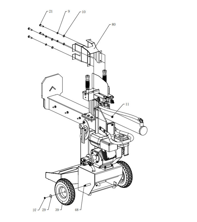
2. Wheel & Cylinder
Assembly
1\. Adjust the beam to a horizontal position and fix it with lock system.
2\. Assemble the cylinder and wedge protector to the beam by using Hex Bolt (#21), Spring
Washer (#9) , Flat Washer (#10) and Nut (#11).
3\. Assemble 2pcs wheels (#39) to the main body by using wheel shaft (#48), Flat Washer (#29)
and Nut (#37).
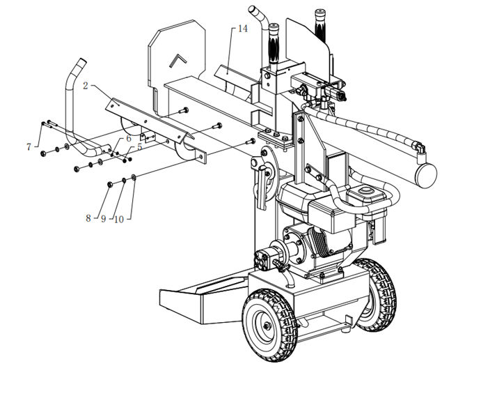
3. Log Guide & Engine
Assembly
1\. Assemble the Left and Right Log Guide (#2 & #14) by using Nuts (#8), Spring Washer (#9)
and Flat Washer (#10).
2\. Assemble the Log guard (#4) by using Nuts (#5), Flat Washer (#6) and Bolt (#7).
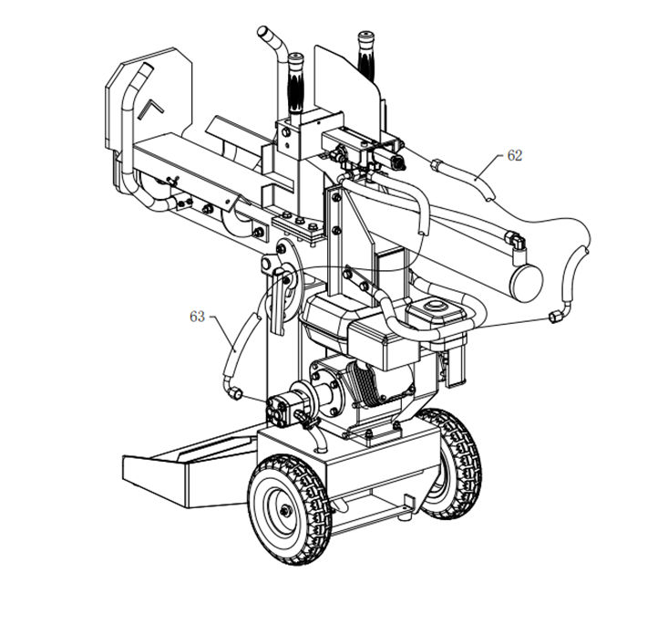
4. Hydraulic Hoses Assembly
1. Connect the high-pressure hydraulic hose (#63). Attach one end to the
control valve inlet (pre-installed at the factory) and the other end to the engine gear
pump. 2. Connect the second hydraulic hose (#62). Attach one end to the
control valve outlet (also pre-installed at the factory) and the other end to the oil
tank. 3. Install the oil pipe onto the gear pump and secure it with clamp
(#43). 4. Connect the control valve to the cylinder using the oil pipe
(#61).
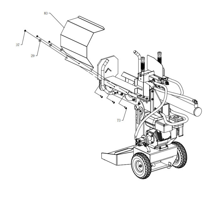
5. Protection Cover Assembly
1. Assemble the Protection Cover (#83) by using Nuts (#37),
Flat Washer (#29) and Hex Bolt (#73).
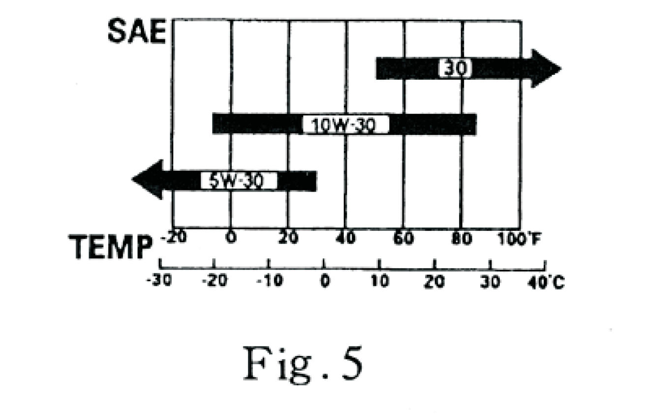
6. Engine Oil
CAUTION:
Engine oil quality is crucial for performance and engine life.
Do not use oil mixed with additives or two-stroke gasoline — this can cause
insufficient lubrication and serious engine damage.
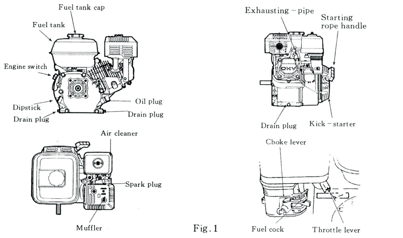
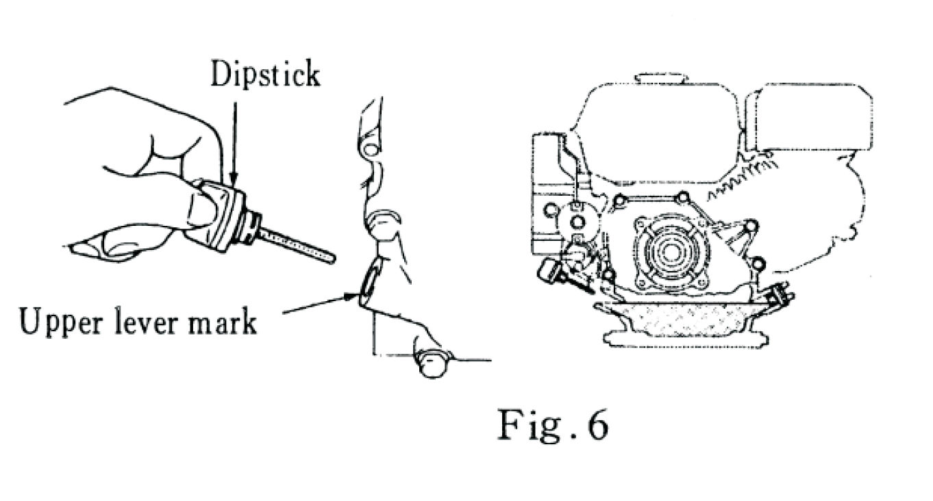
To Check and Fill Engine Oil:
1. Place the machine on a level surface and make sure the engine is
stopped. 2. Remove the dipstick and wipe it clean. 3. Insert the
dipstick into the oil filler neck without screwing it in, then remove it to check the
oil level. 4. If the oil is below the lower level mark, add
recommended SAE 10W–30 (API SF or higher) engine oil until it reaches the
upper level mark. 5. Reinstall the dipstick securely.
7. Air Cleaner
CAUTION: Never run the engine without an air cleaner - dust and debris can cause serious
internal wear.
Types of Air Cleaners:
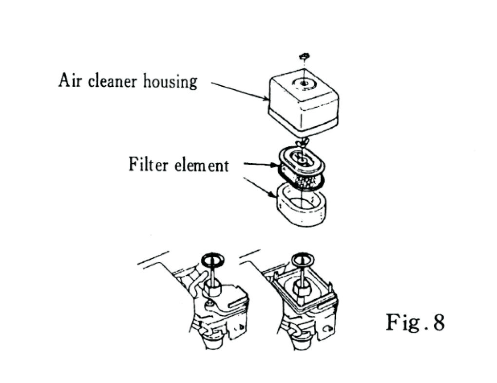
a) Double-Core Type (Fig.8)
1. Remove the air cleaner housing cover. 2. Check the filter element for
dirt or damage. Clean or replace it if necessary.
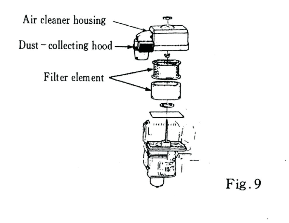
b) Dust-Collecting Type (Fig.9)
1. Remove the dust-collecting hood and check both the hood and filter
element. 2. Clean or replace if dirty or damaged. 3. Remove any dust found inside the
dust-collecting hood.
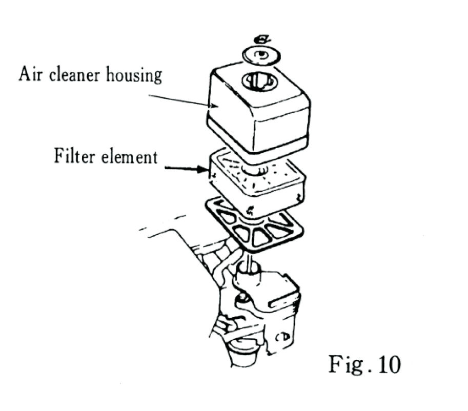
c) Semi-Dry Type (Fig.10)
1. Remove the housing and inspect the filter for dirt or debris. 2. Clean or replace if
necessary.
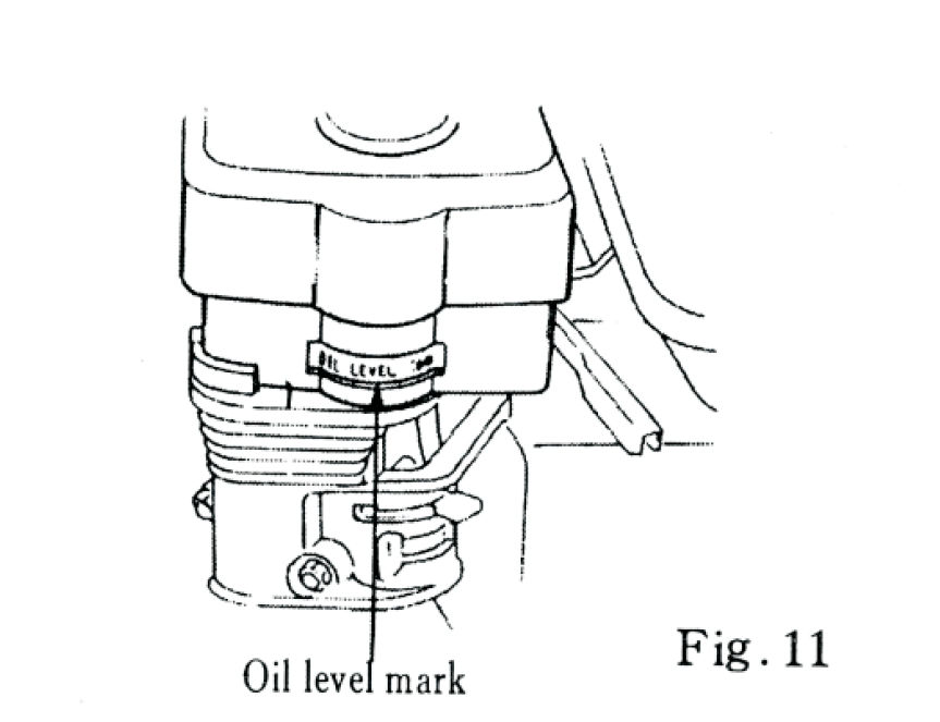
d) Oil-Bath Type (Fig.11)
1. Remove the air cleaner housing and filter core. 2. Check the oil level and oil quality in
the cleaner base. 3. If low or dirty, replace the oil with engine oil (same grade as
engine) up to the oil level mark.
8. Fuel and Fuel Tank
CAUTION:
Always use unleaded gasoline with an octane rating of 86 or
higher.
Never use fuel/oil mixtures or stale, contaminated fuel.
Avoid fuels containing more than 10% ethanol or 5%
methanol — these can damage fuel system components.
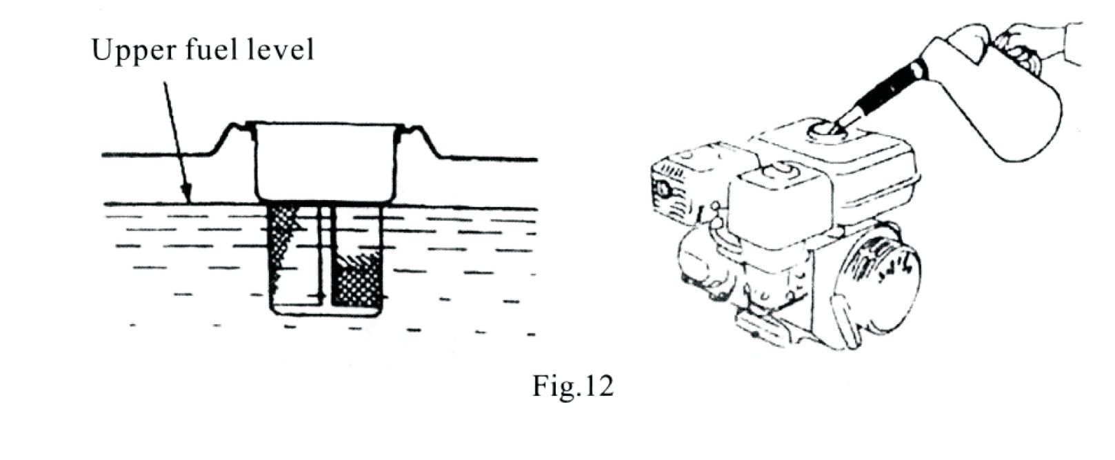
To Check and Fill Fuel:
1. Remove the fuel filler cap. 2. Ensure fuel is clean and free of water or
debris. 3. Fill up to the upper fuel level mark (do not overfill). 4.
Replace the cap securely.
Fuel Tank Capacity: 2.5 litres for 196F / 3.6 litres for 168F engines.
Tip: If you hear knocking or pinging during steady operation, switch to a
different brand of gasoline. Continuous knocking can damage the engine.
9. Fuel Safety Warnings
Gasoline is highly flammable and explosive under certain conditions.
Refuel only in a well-ventilated area with the engine stopped.
Do not smoke or allow flames or sparks nearby while refuelling.
Avoid overfilling the tank - leave some space in the filler neck for fuel
expansion.
After refuelling, tighten the fuel cap securely.
Wipe away any spilled fuel before starting the engine.
Avoid prolonged contact with fuel or inhaling fumes.
Keep fuel out of reach of children.
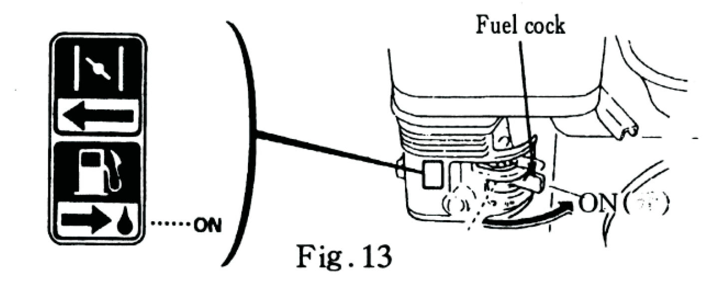
10. Starting the Engine
1. Turn on the fuel supply \- Set the fuel cock to the
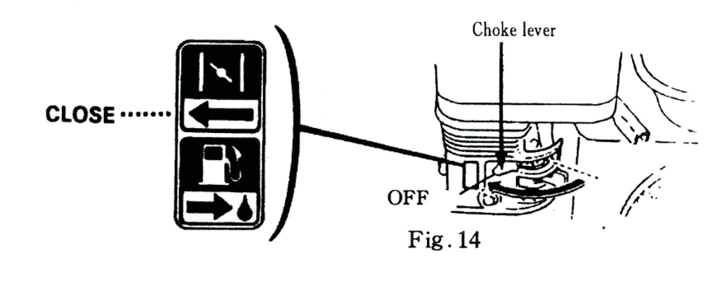
ON position.(See Fig. 13) 2. Close the choke
\- Move the choke lever to the CLOSE position.(See Fig.
14)
> Note: If the engine is already warm, closing the choke is not
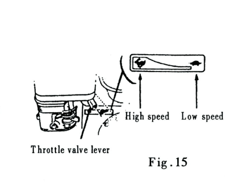
necessary. 3. Set the throttle Move the throttle lever
slightly to the left (toward higher speed).(See Fig. 15) 4.
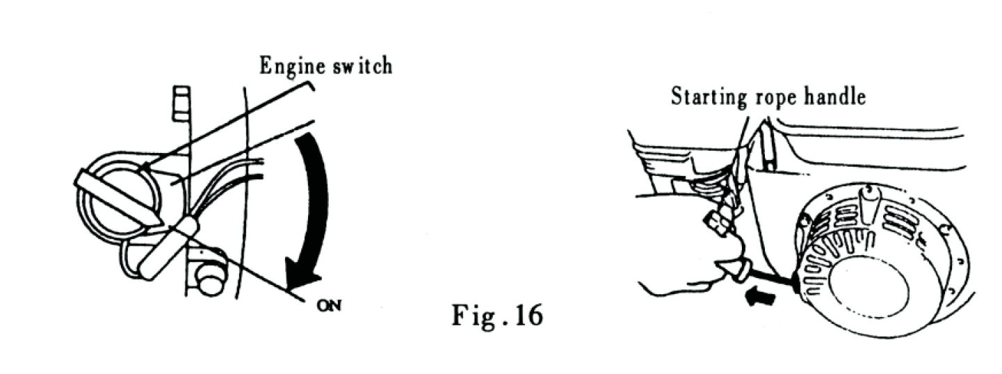
Start the engine \- Turn the engine switch to the
ON position.(See Fig. 16) \- Pull the starter
handle slowly until you feel resistance, then pull quickly and firmly.(See Fig.
16) 5. Release the starter handle carefully >
CAUTION:Do not let the handle snap back. Guide it back gently to prevent damage
to the engine or starter mechanism.
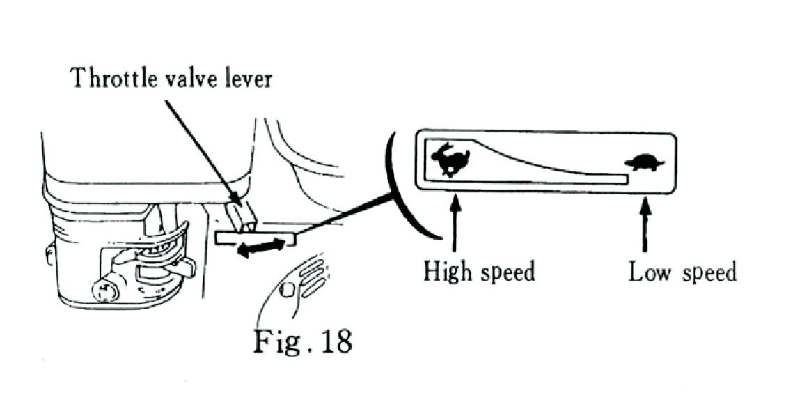
11. Engine Operation
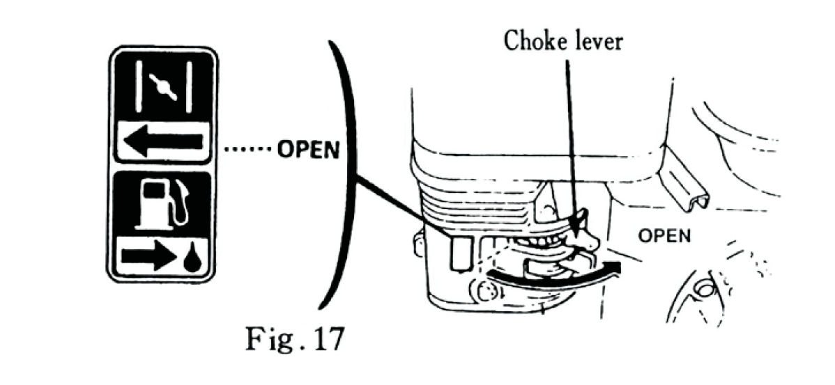
1. Warm up the engine Allow the engine to run for a short period before
use. Then move the choke lever to the OPEN position. (See
Fig. 17) 2. Set operating speed Adjust the throttle
lever to achieve the desired engine speed for your operation. (See Fig. 18)
12. Safety Warnings
Engine Oil Alarm:
This engine is equipped with an Oil Alert System that stops the engine
automatically if the oil level becomes too low.
Running the engine without enough oil can cause severe damage.
> CAUTION: > > If the engine fails to start, check the oil
level first before inspecting other components. > > Always maintain proper
oil levels to ensure reliable operation.
Operating on Highlands:
When operating above 1,830 m (6,000 ft), air density decreases, making the
standard fuel mixture too rich. This can cause poor performance and increased fuel
consumption.
To adjust for high altitude operation:
1. Have a qualified technician replace the carburettor's main jet with a
smaller one. 2. Adjust the idle screw as needed.
> CAUTION: > > Power output decreases about 3.5%
for every 305 m (1,000 ft) increase in altitude. > > Engines
modified for high altitude may run too lean and overheat at lower altitudes. > Ask your
dealer to return the carburettor to standard settings if you move to a lower altitude.
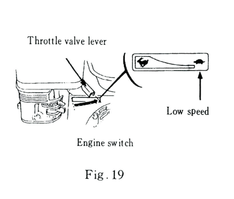
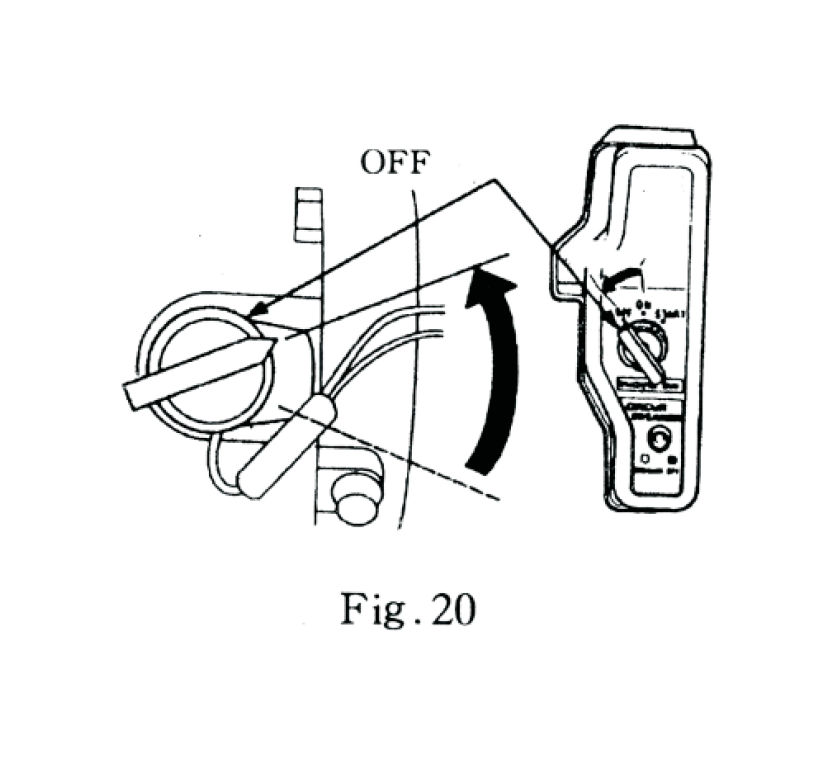
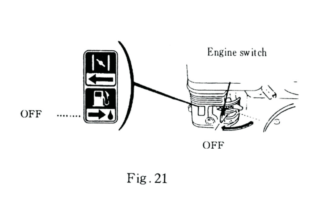
13. Stopping the Engine
In an emergency, turn the engine switch to OFF immediately.
For normal shutdown:
1. Move the throttle lever to the LOW SPEED position.
(See Fig. 19) 2. Turn the engine switch to OFF.(See Fig. 20) 3. Set the fuel cock to the OFF
position. (See Fig. 21)
14. Exhaust Control System
The engine emits carbon monoxide (CO), nitrogen oxides (NOₓ), and hydrocarbons (HC). Proper
maintenance and fuel use help minimize these emissions.
To keep emissions within standard levels:
1) Maintenance
Follow the Maintenance Schedule regularly (see Maintenance Section).
Service more frequently under heavy load, dusty, or high-temperature conditions.
2) Replacement of Parts
Use only genuine or equivalent-quality replacement parts.
Using inferior components can reduce emission control effectiveness.
3) Modifying the Exhaust System
> WARNING: Do not tamper with or modify the air intake or exhaust
systems. > Alterations can increase emissions, violate legal regulations, and damage the
engine.
4) Problems Affecting Exhaust Emissions
Contact your dealer if you notice any of the following:
Difficulty starting or stalling
Unstable idle
Excessive smoke or fuel consumption
Poor ignition or backfiring
Engine knocking or pinging
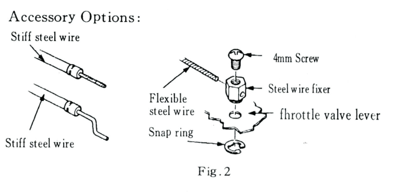
15.
The throttle and choke valve levers both have holes designed for attaching optional steel
control wires. Figures 2, 3, and 4 illustrate how to install either a solid
(stiff) steel wire or a flexible (meshed) steel wire for remote
operation.
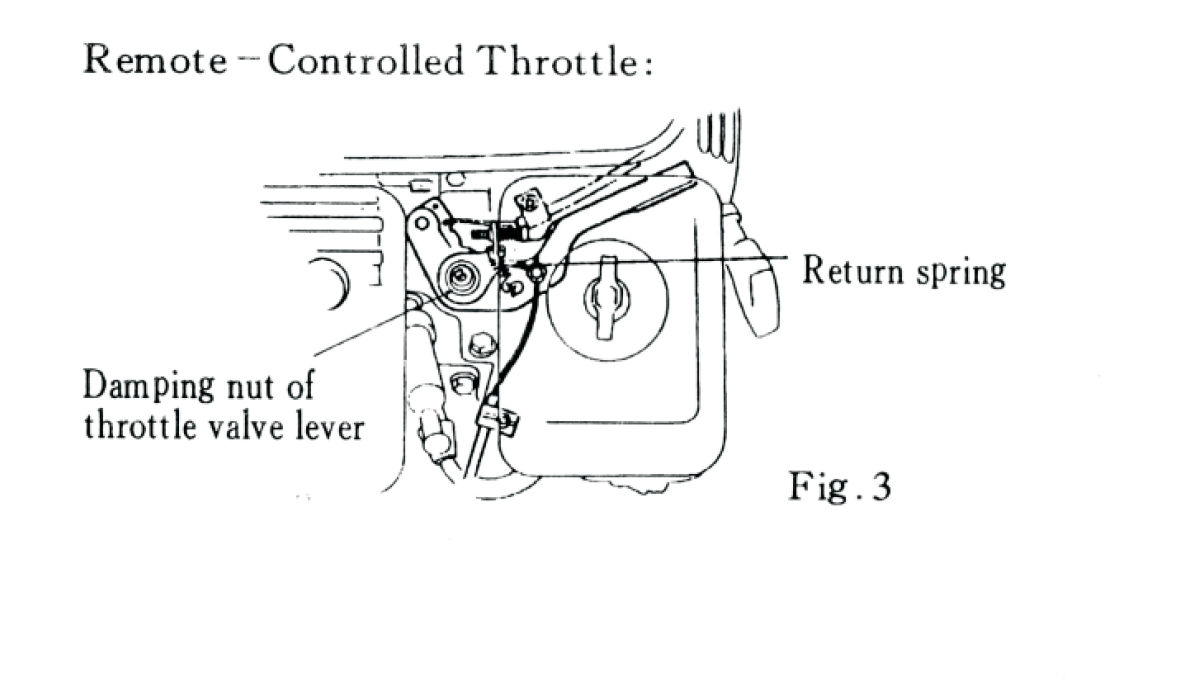
If using a flexible steel wire, a return spring must be installed to ensure
proper throttle return.
If needed, you can slightly loosen the damping nut on the throttle valve lever
when connecting the throttle for remote operation. This allows smoother control movement.
1. Attach the steel wire to the throttle valve lever using the steel
wire fixer and 4 mm screw. 2. If using a flexible wire, install
the return spring to assist the throttle in returning to idle. 3. If the
throttle movement feels tight, loosen the damping nut on the throttle valve
lever slightly.
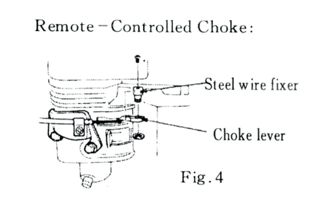
Remote-Controlled Choke Installation (Figure 4):
1. Attach the steel wire to the choke lever using the steel wire
fixer and 4 mm screw. 2. Ensure the wire moves freely and can
fully open and close the choke valve.
16.
1\) Load the log securely onto the beam and position it firmly against the wedge before
operating.
2\) Serious accidents can happen when other people are allowed inside the work zone. Keep the
work zone clear of all other persons while operating the control valve to prevent serious
injury.
3\) Use both hands to push the control valve handle forward to initiate the
log splitting action.
4\) Use both hands to pull the control valve handle backward to return the
wedge to its original position.
5\) Never place any part of your body near the wedge or beam slide during operation; the wedge
poses a severe crush hazard and can cut through skin or break bones.
6\) Remove all split wood and debris from the work zone immediately after each operation to
maintain a safe workspace.
7\) Do not wear loose clothing during operation, as it may become entangled in moving parts.
8\) Operate the log splitter only during daylight hours or in a well-lit
environment to ensure clear visibility and safe operation.
17. Machine Maintenance
Always place the log splitter in maintenance mode before performing any servicing by turning
off the engine and moving the control valve handle forward and backward to relieve hydraulic
pressure.
After any maintenance work, make certain that all guards, shields, and safety features are
securely reinstalled before using the machine.
Inspect all hoses before each use for exposed wire mesh or leaks and replace any worn or
damaged hoses before starting the engine.
Inspect all hydraulic fittings before each use for cracks or leaks and replace any damaged
fittings before starting the engine.
Check all nuts and bolts before each use to ensure they are secure and tightened correctly.
Apply grease to the beam surface before each use to maintain smooth performance.
Remove all debris from moving parts before each use to prevent damage and ensure safe
operation.
18. Engine Maintenance
Maintenance Schedule:
To keep the engine in good condition, follow the recommended maintenance schedule in the table
below.
| Item | Action | Frequency | | :----------------------- | :----------------------- |
:-------------------------------------------- | | Engine Oil | Oil level check | Before every
use | | Reduction Gear Oil | Oil level check | Before every use | | Air Cleaner | Check /
Clean / Replace | Before every use / Every 3 months / Each year | | Deposit Cup | Clean |
Every 6 months | | Spark Plug | Clean / Replace | Every 6 months / Each year | | Valve
Clearance | Check - adjust | Each year | | Fuel Tank & Fuel Filter | Clean | Each year
| | Fuel Supply Line | Check | Every 2 years (Replace if necessary) |
19. Replacing Engine Oil
General Safety:
Always stop the engine before performing maintenance.
If servicing is required while the engine is running, ensure proper ventilation.\
Engine exhaust contains toxic carbon monoxide, which can cause serious injury
or death if inhaled in an enclosed area.
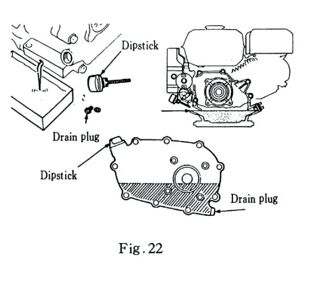
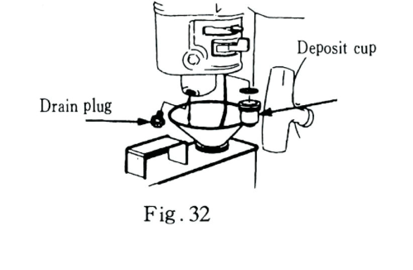
To Drain and Replace Oil:
1. Start the engine and let it run for a few minutes to warm up. This helps the oil drain more
easily. 2. Stop the engine and place an oil pan under the drain plug. 3.
Remove the oil filler cap and drain plug (see Fig. 22). 4.
Allow all oil to drain completely, then reinstall and tighten the drain plug securely. 5.
Refill with the recommended SAE 10W–30 oil up to the upper mark on the
dipstick. Crankcase oil capacity: 0.6 L Reduction gear oil
capacity (if equipped): 0.5 L 6. Reinstall the dipstick securely.
> NOTE: Dispose of used oil properly. Take it to an authorized recycling
facility — do not pour oil into drains or onto the ground.
20. Servicing the Air Cleaner
A clean air filter ensures proper engine performance and protects internal parts from dust.
WARNING: Never run the engine without the air cleaner. Dust and dirt can
cause rapid engine wear or failure. Do not use gasoline or flammable solvents to clean the
air filter.
*
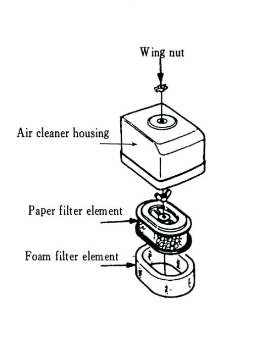
a) Double-Core Type (Fig.23)
1. Remove the wing nut and take off the air cleaner cover. 2. Check the two filter
elements (foam and paper). Replace if damaged. 3. Wash the foam
filter in warm, soapy water or a non-flammable cleaning solvent. Rinse and let dry
completely. 4. Lightly coat the foam filter with clean engine oil, then squeeze out excess
oil. 5. Tap the paper filter gently to remove dust. Replace if heavily
soiled. 6. Reassemble and tighten the wing nut securely.
*
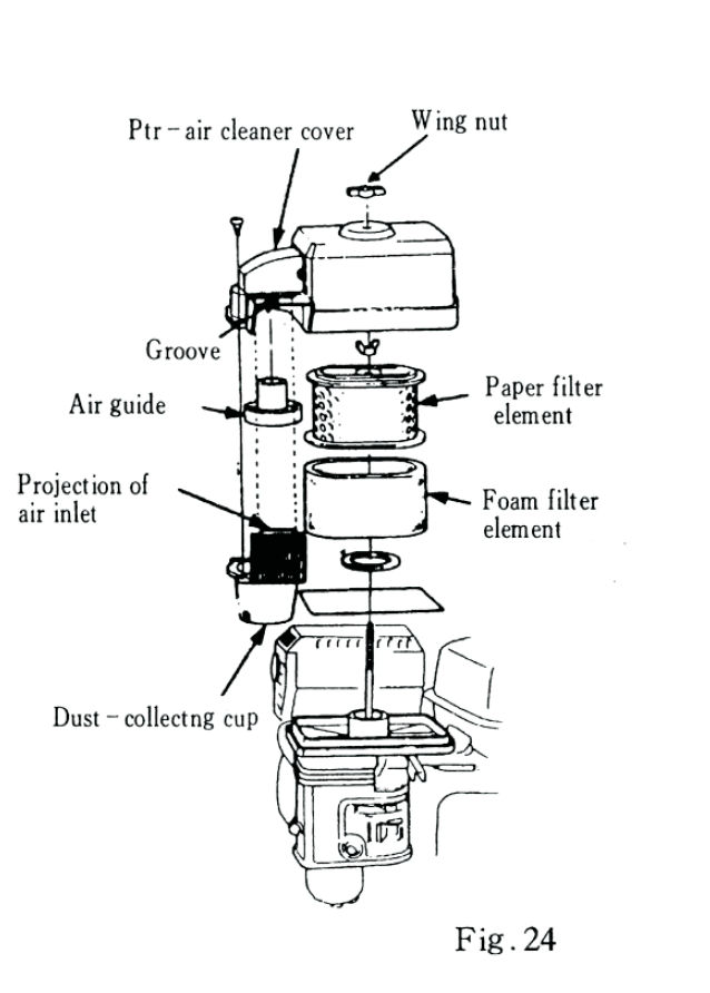
b) Dust-Collecting Type (Fig.24)
1. Remove the wing nut and open the air cleaner housing. 2. Remove and inspect both filter
elements for damage. 3. Clean the foam element as above. 4. Blow compressed air (under 30
psi) from inside to outside of the paper filter to remove dust. Avoid cleaning with a brush, as
brushing may force dust into the core fibre. Replace if necessary. 5. To clean the
dust-collecting cup, remove and wash parts with water and then dry. Ensure the
dust-collecting cover is correctly reinstalled to prevent dust from entering
the air inlet. 6. Reassemble securely.
*
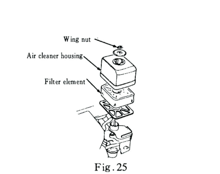
c) Semi-Dry Type (Fig.25)
1. Remove the wing nut and air cleaner cover. Take out the filter element. 2. Clean with
warm, soapy water or a non-flammable cleaning solvent. Rinse and dry completely. 3. Lightly
oil the element and squeeze out excess oil. 4. Reinstall all components properly.
*
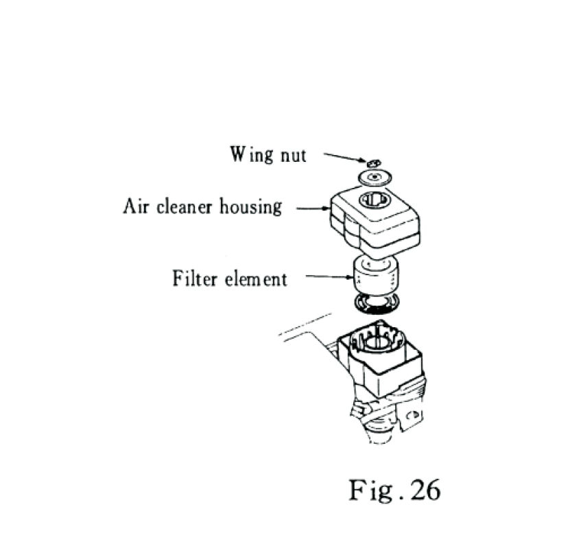
d) Oil-Bath Type (Fig.26)
1. Remove the wing nut and housing. Take out the filter element. 2. Clean the element with
warm, soapy water or solvent, then dry. 3. Remove any dirt or debris from the cleaner
base. 4. Refill the oil bath to the marked oil level using clean engine
oil. 5. Reassemble and secure the air cleaner.
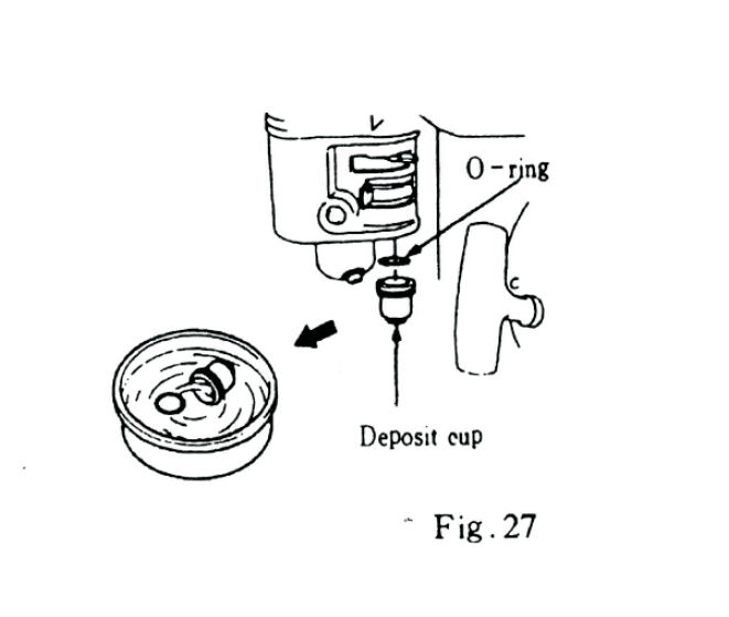
21. Cleaning the Fuel Deposit
Cup
1. Turn the fuel valve to OFF. 2. Remove the deposit cup
and O-ring. 3. Wash both parts in a non-flammable cleaning solvent, then dry
completely. 4. Reinstall and check for leaks. 5. Turn the fuel valve ON
to verify proper operation.
> WARNING: > > Gasoline and its vapours are highly
flammable. Keep sparks, flames, and cigarettes away. > Always ensure the area is
well ventilated. > * After reinstalling, check for leaks before starting the engine.
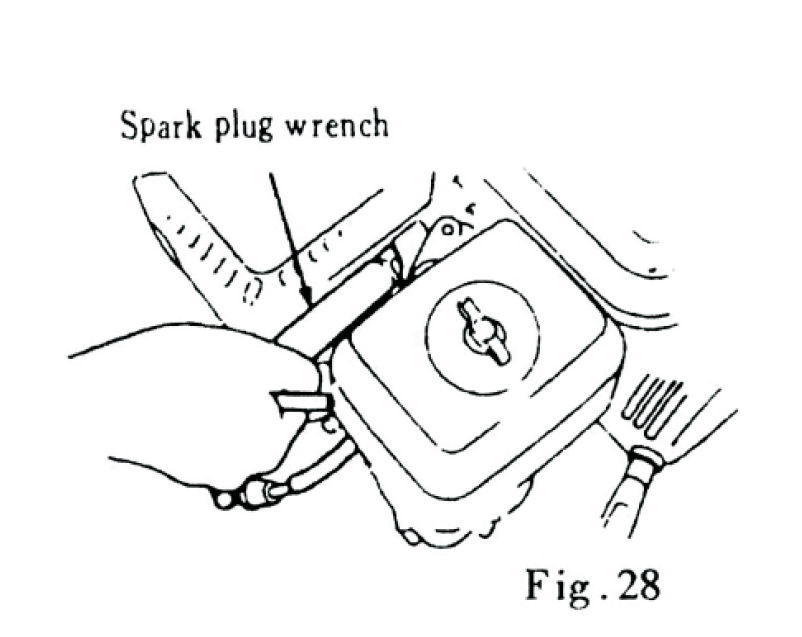
22. Spark Plug Maintenance
Use the recommended spark plug type: F7TC / F6RTC
To Inspect and Clean:
1. Remove the spark plug cap and use a wrench to take out the plug. 2. Inspect for carbon
build-up or wear. Clean the spark plug with a wire brush. If the insulator is damaged, replace
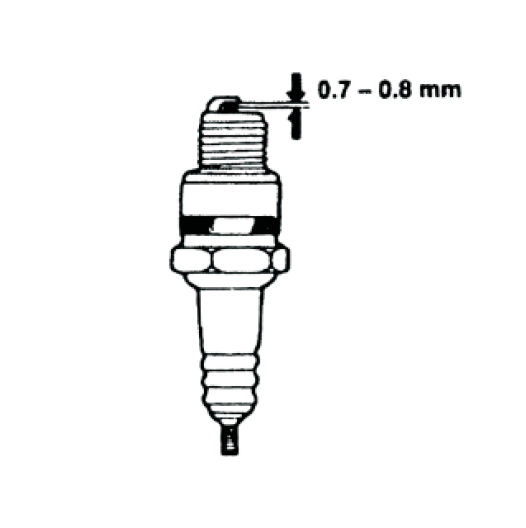
the spark plug instead. 3. Check the gap using a feeler gauge - it should be
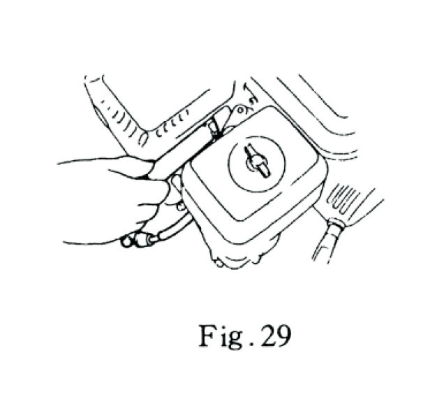
0.7–0.8 mm (Fig.29). 4. Reinstall the plug by hand, then tighten:
* New plug: Tighten an additional ½ turn after the gasket
contacts the seat.
* Reused plug: Tighten an additional ⅛ to ¼ turn after the
gasket contacts the seat.
> CAUTION: > > Tighten securely — loose plugs can overheat
and damage the engine. > > Use only recommended plug types to ensure proper
ignition and longevity.
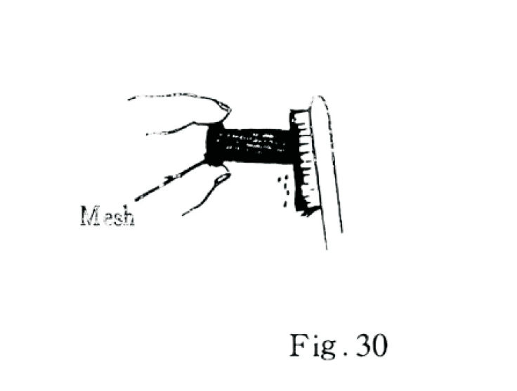
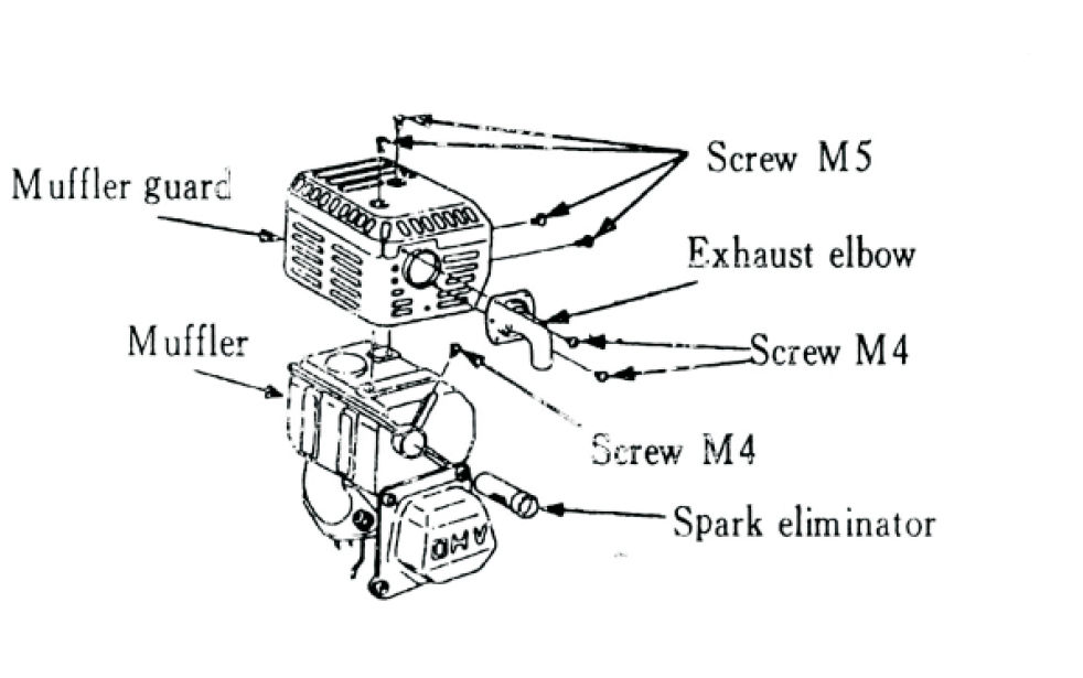
23. Spark Arrestor (Optional)
The spark arrestor prevents sparks from exiting the muffler. Clean it every 100
hours of operation.
To Service:
1. Allow the muffler to cool completely. 2. Remove the screws securing the arrestor and
muffler cover. 3. Clean any carbon deposits from the arrestor screen with a brush. 4.
Reinstall all parts in reverse order of removing them.
> CAUTION: > > * The muffler stays very hot during and after
operation. Do not touch until it has completely cooled. > > - Do not damage the mesh
screen. > - Replace any damaged spark arrestor before use.
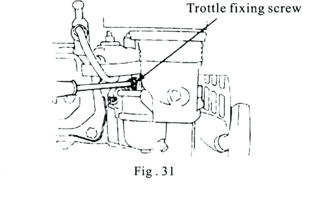
24. Carburettor Idle Adjustment
To ensure smooth idling:
1. Warm up the engine to normal operating temperature. 2. Turn the throttle fixing
screw to achieve a stable idle speed of 1700 ± 150 RPM.
> Adjust gradually while listening to engine response to avoid stalling or racing.
25. Transport
Turn the fuel switch OFF before transporting the engine.
Allow the engine to cool completely before moving to prevent burns or fire
hazards.
> CAUTION: Keep the engine upright during transport to prevent fuel
spillage. Spilled fuel or vapours can ignite and cause a fire.
26. Storage
If the engine will not be used for an extended period, store it properly to prevent corrosion
and ensure easy restarting later. Always store in a clean, dry, and dust-free location.
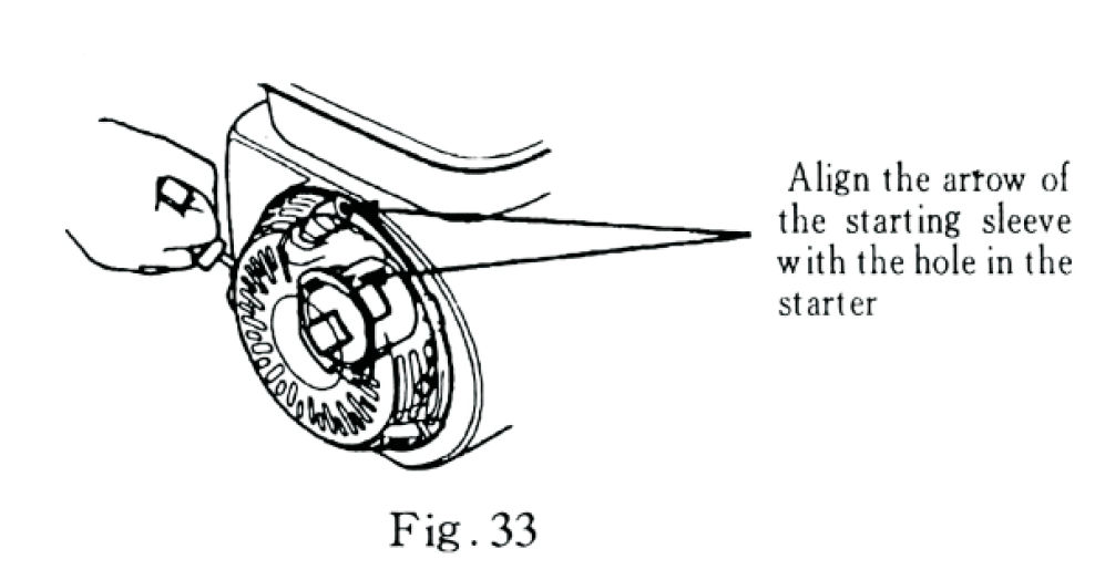
1. Drain and replace the engine oil. (See Fig. 32) 2. Remove the
spark plug, and pour about 5–10 ml of clean engine oil into the
spark plug hole. Pull the recoil starter slowly several times to distribute the oil inside
the cylinder, then reinstall the spark plug. 3. Gently pull the recoil
starter until you feel resistance. Align the arrow on the starter sleeve with the
hole in the starter (Fig. 33). This closes the intake and exhaust valves to prevent rust. 4.
Cover the engine to keep out dust and moisture.
27. Removal from Storage
Before restarting after storage, follow the service schedule below:
| Storage Time | Required Service | | :------------- |
:---------------------------------------------------------------------------------------- | |
Within 1 month | Drain any old fuel, refill with fresh fuel, and start the engine. | | 1-2
months | Drain old fuel, refill with fresh fuel, and empty the deposit cup. | | 2-12 months |
Drain fuel from the carburettor and deposit cup. Refill with fresh fuel. | | Over 12 months |
Drain old fuel and oil completely. Refill with fresh oil and fuel, then start the engine. |
WARNING:
Fuel is highly flammable. Always keep flames and sparks away during maintenance.
Dispose of old fuel responsibly - take it to an approved recycling centre.
Never pour fuel or oil into the ground or drains.
28.
Important: Before carrying out any maintenance or repair work on the log
splitter, all residual energy in the pressurised hydraulic system must be released.
Hydraulic fluid can remain highly pressurised even when the engine is off. Escaping pressurised
fluid may penetrate the skin and cause severe injury.
To safely release residual hydraulic pressure:
1. Shut off the engine. 2. Move the control valve back and forth, from one end of travel to
the other, at least four times. 3. Hold the valve at each end of travel for three seconds.
WARNING – Skin Injection Hazard High-pressure hydraulic fluid can
penetrate the skin and cause serious injury, including possible amputation.
Ensure all fittings are secure before applying pressure.
Always relieve system pressure before servicing.
Never check for leaks with your hand. Use a piece of cardboard or wood instead.
If hydraulic fluid is injected into the skin, seek immediate surgical
treatment.
29. Machine Troubleshooting
| Problem | | | :----------------------------------------------------- |
:---------------------------- | | Cylinder rod will not move | SOLUTION: A, D, E, H, J | |
Slow cylinder shaft speed when extending or retracting | SOLUTION: A, B, C, H, I, K, L | |
Wood will not split or splits extremely slow | SOLUTION: A, B, C, F, I, K | | Engine bogs
down during splitting | SOLUTION: G, L | | Engine stalls under low load condition | SOLUTION:
D, E, L, M |
| Cause | Solution | | :---------------------------------------- |
:------------------------------------------------------------------------------- | | A -
Insufficient oil to pump | Check oil level in oil tank | | B- Air in oil | Check oil level in
oil tank | | C- Excessive pump inlet vacuum | Check pump inlet hose for blockage or kinks
| | D- Blocked hydraulic lines | Flush and clean the splitter hydraulic system | | E-
Blocked control valve | Flush and clean the splitter hydraulic system | | F- Low control
valve setting | Adjust control valve with a pressure gauge | | G- High control valve setting
| Adjust control valve with a pressure gauge | | H- Damaged control valve | Return control
valve for authorised repair | | I- Internal control valve leak | Return control valve for
authorised repair | | J- Internal cylinder leak | Return control valve for authorised repair
| | K- Internally damaged cylinder | Return control valve for authorised repair | | L-
Engine Control out of adjustment | Adjust idle control nuts | | M- Engine is loaded during
idle down mode | Use shorter log length (20" or less) to allow engine to speed up before
contact. |
30. Engine Difficult to Start
| Possible Cause | Remedy | | :--------------------------------------- |
:----------------------------------------------------------- | | Fuel valve closed or tank
empty | Open fuel valve and refill fuel | | Fuel line or carburettor blocked | Clean and
remove blockage | | Air vent in fuel cap clogged | Clean vent | | Spark plug dirty, worn,
or gap incorrect | Clean or replace spark plug and set correct gap (0.7-0.8 mm) | | Fuel is
stale or contaminated | Replace with fresh, clean fuel | | Choke not used properly | Close
choke for cold start; open gradually after starting |
31. Low Engine Power Output
| Possible Cause: | Remedy: | | :---------------------------------------- |
:-------------------------------------- | | Incorrect ignition timing | Adjust ignition
advance angle | | Air leak in fuel line | Inspect and reseal fuel connections | | Main jet
blocked or adjusted incorrectly | Clean jet and reset to factory setting | | Air filter
clogged | Clean or replace filter | | Too much carbon build-up | Remove and clean combustion
chamber | | Exhaust blocked | Clean or replace muffler |