monstershopmonstershop.co.uk
Instructions by monstershopT-Mech 7.5hp Petrol Rotavator Tiller
monstershop

T-Mech 7.5hp Petrol Rotavator Tiller

T-Mech 7.5hp Petrol Rotavator Tiller
Before you start
Safety Advice and WarningsGPSR Information Parts
Steps
1. Installation of the Power Rotavator2. Installation and Adjustment of Backstay Cables3. Inspection and Refuelling 4. Adjustment Methods and Data 5. Operation 6. Maintenance of the Power RotavatorSection 7

No results

monstershop
monstershop / T-Mech 7.5hp Petrol Rotavator Tiller
T-Mech 7.5hp Petrol Rotavator Tiller
monstershop

Instructions by

monstershop

T-Mech 7.5hp Petrol Rotavator Tiller

This manual provides comprehensive instructions for assembling, installing, and using the 7.5 HP Petrol Rotavator. It includes detailed specifications, safety advice, user guides, maintenance schedules, and troubleshooting tips to ensure optimal performance and safety.

Product Information

7.5hp Petrol Rotavator

7.5hp Petrol Rotavator

The T-MECH 7.5hp Petrol Rotavator is a powerful and reliable solution for demanding tilling tasks, designed to tackle a wide range of soil conditions with ease. Equipped with a robust 212cc engine delivering 7.5hp, this machine features an adjustable tilling width of 800–1000mm and a depth range of 100–300mm, ensuring efficient ground preparation. The gear transmission, recoil start, and intuitive shift options offer smooth operation, while the up/down adjustable handlebar and durable 4.0-8 tyres provide enhanced manoeuvrability. With a generous fuel tank and 12 heavy-duty blades across three groups, the T-MECH rotavator is built for performance and durability.
SKU
216395

Safety Advice and Warnings

Safety Advice and Warnings

1. Safety Requirements

1.1 General Requirements

Before using the machine, the operator must carefully read and understand the instruction manual and strictly follow the specified procedures for break-in, adjustment, operation, and maintenance.

1.2 Pre-Operation Inspection

Before starting the machine, check the following items:

1.2.1 Oil Inspection
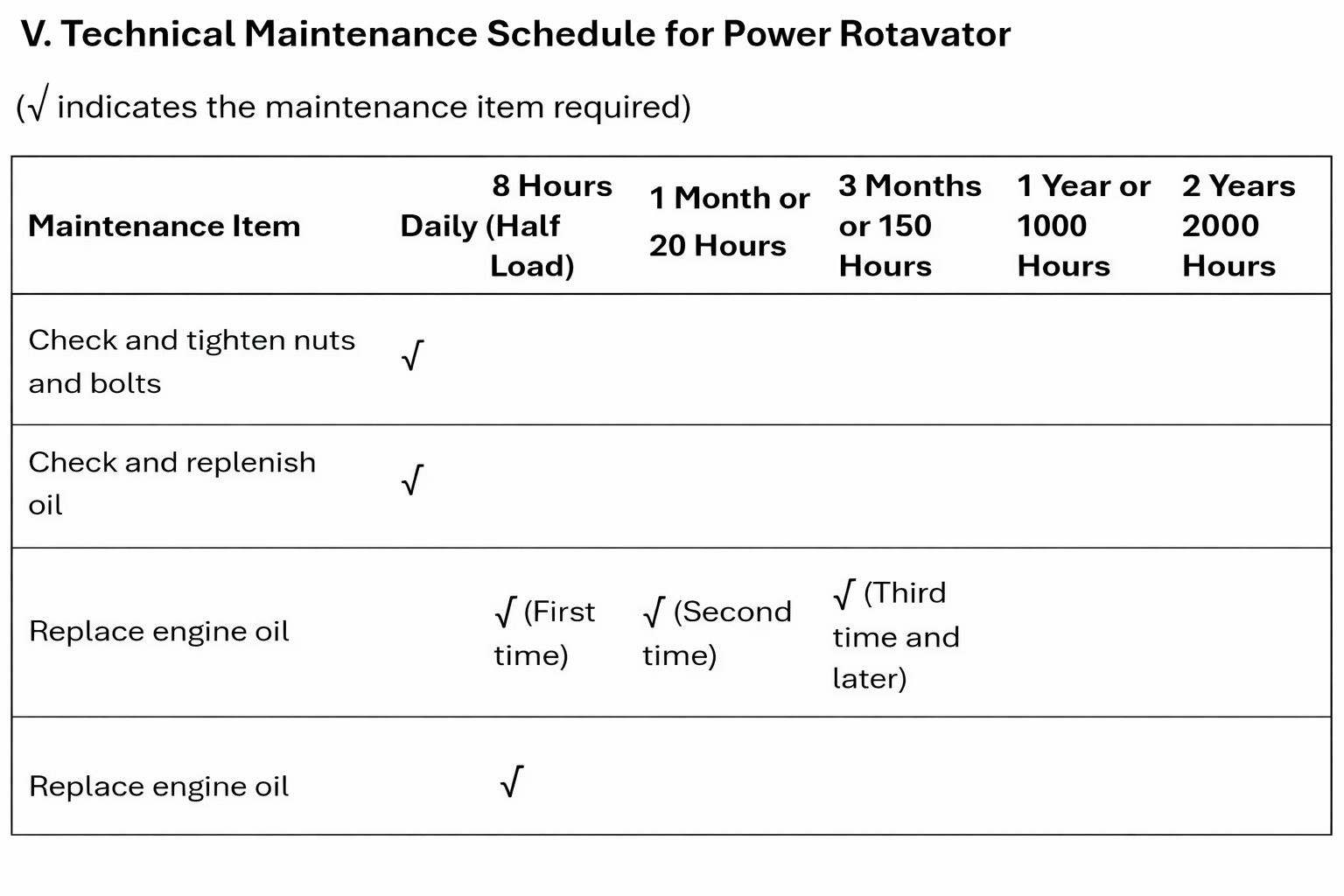
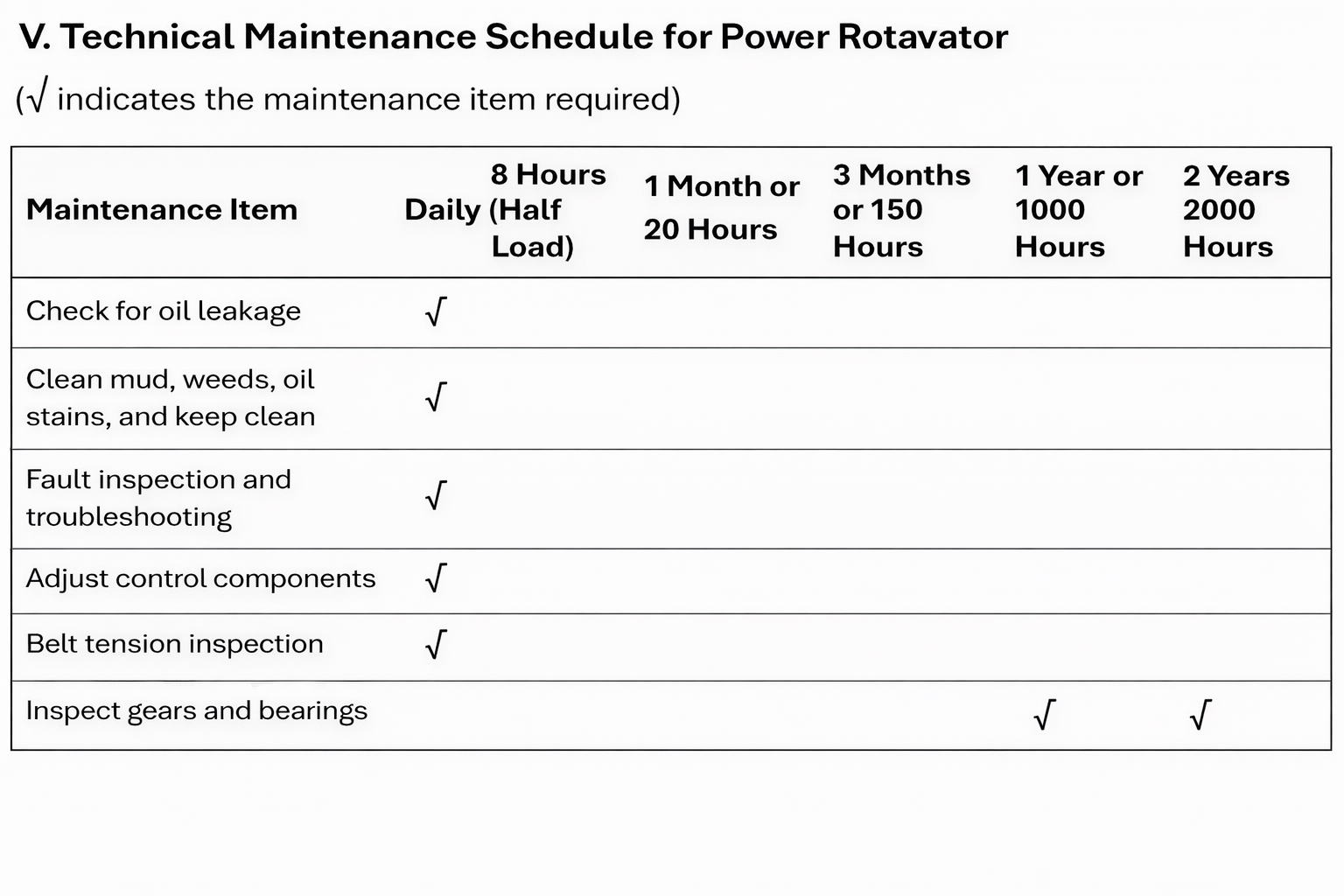
Check whether there is oil leakage from the engine crankcase and transmission case. Verify the oil level and oil quality in both units. Refill or replace with clean engine oil as required. Ensure that all lubrication points are properly lubricated.

⚠ Danger 1.2.2 Fuel Safety
When refuelling:

  • Use clean, qualified fuel only.
  • Refuel only when the internal combustion engine is stopped and in a well-ventilated area.
  • Ensure fuel does not come into contact with hot surfaces, electrical components, or rotating parts.
  • Do not overfill the fuel tank to prevent spillage.
  • Check for fuel leakage after refueling. If fuel is spilled, wipe it dry completely before starting the machine.
  • Tighten the fuel tank cap securely after refueling.
  • Smoking and open flames are strictly prohibited in refueling areas, fuel storage areas, and work sites to prevent fire hazards.

1.2.3 Fastener and Rotation Check
Check whether all fasteners are securely tightened. Ensure that moving parts are not loose, rubbing, or jammed, and confirm that rotation direction matches the indicated markings.

1.2.4 Safety Guards and Labels
Check that all exposed rotating and moving parts are equipped with reliable safety guards and safety warning signs, and that all markings are complete and clearly visible.

1.2.5 Component Condition
Check the clutch engagement condition. Inspect working components such as the rotary Rotavator blades and clutch for cracks, deformation, or excessive wear.

⚠ Warning 1.2.6 Abnormal Conditions
Any abnormal condition must be eliminated before test operation. During trial operation, there should be no abnormal noise, friction, or excessive vibration. The rotational speed must comply with regulations, and overspeed operation is strictly prohibited. Replacement of safety-related parts must be carried out according to the instruction manual or under the guidance of qualified maintenance personnel.

*

1.3 Operator Qualifications

⚠ Warning: Minors and individuals who have not received proper training in power Rotavator operation are strictly prohibited from operating the machine.

1.4 Operator Condition

⚠ Warning: Do not operate the machine while intoxicated, ill, or excessively fatigued.

1.5 Clothing and Personal Safety

⚠ Warning: Operators must wear properly fitted clothing with cuffs secured. Long hair must be tied up and covered with a protective cap.

1.6 Modification Prohibition

⚠ Warning: Do not modify any parts that affect machine safety or operation. Protective covers must not be removed, shortened, or altered. Operators must remain focused during operation.

1.7 Safe Start and Load Control

⚠ Warning: The power Rotavator must only be started after confirming it is safe to do so. When the engine temperature is low after startup, heavy-load operation is not permitted, especially for new or overhauled machines.

1.8 Rotary Tillage Restrictions

⚠ Warning: A power Rotavator fitted with rotary blades must not be driven on concrete surfaces, stone slabs, or gravel piles. During rotary tillage, avoid striking hard objects such as stones to prevent blade damage.

1.9 Monitoring During Operation

⚠ Warning: During operation, closely observe the working condition and sounds of all components. Loose connections or abnormal sounds are not permitted. If abnormalities occur, immediately cut off power and stop the machine for inspection. Troubleshooting while the machine is running is strictly prohibited.

1.10 Stability

⚠ Warning: Take precautions to prevent the power Rotavator from tipping over during operation.

1.11 Reverse Operation Safety

⚠ Warning: Reverse gear operation is prohibited when the operator is within 2 meters of the field edge.

1.12 Resistance Bar Removal

⚠ Warning: Before engaging reverse gear, the resistance bar must be removed.

1.13 Oil Leakage During Operation

During operation, observe whether oil leakage occurs at the engine, transmission case, or other components. If leakage is found, immediately stop the machine and cut off power for inspection. Open flames must not be used during inspection to prevent fire. Repairs must be carried out promptly to prevent environmental pollution and food safety risks.

1.14 Cleaning Obstructions

When removing entangled grass or mud, shut off the power and ensure the machine has completely stopped. Never remove obstructions from rotary blades by hand or with tools while the machine is running.

1.15 Post-Operation Cleaning

After operation, remove soil, weeds, oil, and debris from the power Rotavator to maintain cleanliness and performance.

1.16 Field Transfer

When transferring between fields, remove the rotary blades and install the walking wheels.

1.17 Regular Inspection

Regularly inspect bolts on rotary blades, bearing housings, and other moving parts for looseness or damage, and tighten or replace them as required.

GPSR Information

UK

  • Manufacturer: Monster Group UK Limited, Monster House 19-23 Alan Farnaby Way, Industrial Estate Sheriff Hutton, York YO60 6PG, England.
  • Person Responsible: Rana Harvey, Monster Group UK Limited, Monster House 19-23 Alan Farnaby Way, Industrial Estate Sheriff Hutton, York YO60 6PG, England. +441347878880

EU

  • Manufacturer: Monster Group BV, Van Heemskerckweg 28A & B, Venlo 5928LL Netherlands.
  • Person Responsible: Rana Harvey, Monster Group BV, Van Heemskerckweg 28A & B, Venlo 5928LL, Netherlands. +441347878880

Parts

Throttle switch assembly

1. Installation of the Power Rotavator

I. Installation of the Power Rotavator

Before leaving the factory, the main body of the power Rotavator has been assembled and tested. However, before using the power Rotavator for farming operations, users should inspect and adjust all mechanisms to ensure optimal performance.

After purchase, the user only needs to complete assembly according to the following steps:

1. Install the walking wheels on both ends of the hexagonal drive shaft at the lower part of the gearbox, securing them with φ8 pins.
2. Install the towing arm onto the towing seat, connect it with the towing shaft, and insert the resistance rod.
3. Assemble the armrest bracket with the armrest support arm and secure it using the lifting locking handle.
4. Fix the mudguard bracket onto the engine bracket and trailer, then install the mudguard.

2. Installation and Adjustment of Backstay Cables

1. Clutch Cable Adjustment

1. Loosen the lock nut on the adjusting screw.
2. Turn the screw clockwise to the shortest position, exposing the armrest frame.
3. Insert the cable head into the clutch cable seat at the rear of the gearbox assembly, ensuring it is seated in the larger hole.
4. Pass the wire rope through the M8 hole in the movable seat of the clutch toggle arm, press the toggle arm appropriately, and hook the cable end into the clutch cable seat.
5. Adjust by loosening the screw and repeatedly engaging and releasing the clutch handle. When the spring force allows the handle to return smoothly, tighten the lock nut.

2. Reverse Gear Cable Adjustment (See Figures 3 and 4)

1. Loosen the lock nut on the adjusting screw.
2. Turn the screw clockwise until the exposed armrest frame is at its shortest.
3. Insert the pull cable into the reverse gear shift shaft on the side, ensuring the cable head fits into the large hole of the shift fork shaft.
4. Rotate the reverse gear toggle shaft clockwise, pass the cable through the opening of the reverse gear cable holder on the transmission side, and ensure the conduit head is seated securely in the cable holder.
5. Loosen the screw and repeatedly operate the reverse gear handle. When the spring force allows the handle to return automatically, tighten the lock nut.

3. Throttle Cable Adjustment

1. Turn the throttle switch clockwise to the minimum position.
2. Pass the steel wire rope of the throttle cable through the guidepost and fixing seat above the diesel engine throttle adjustment plate.
3. Tighten the wire rope and secure it by tightening the fastening bolts on the fixing seat.
4. Repeatedly adjust the throttle switch until the throttle lever on the adjustment plate reaches both maximum and minimum positions smoothly.

3. Inspection and Refuelling

Bolt Inspection:

Check all connecting bolts for looseness and tighten them according to the torque values listed below. For tightening torque of petrol engine bolts and nuts, refer to the petrol engine user manual.

Component Torque (N·M)

Flange and petrol engine 14-19

Flange and Gearbox 27-38

Gearbox main shaft rear-end bolts 10-12

Engine support bracket and travel case bolts 27-38

Travelling mechanism end cover bolts 10.6-15

Travelling mechanism trailer body bolts 27-38

Walking mechanism to gearbox bolts 27-38

Trailer bolts 27-38

Diesel engine base fixing bolts 27-38

Handrail fixing bolts 35-40

Control System Check:

Ensure that all control handles (throttle, clutch, gear shift and reverse gear) operate smoothly without obstruction. Correct any malfunctions found.

Transmission Gear Position:

Place the transmission shift lever in the neutral position.

Engine Oil and Lubrication:

Engine Oil - Fill the engine crankcase with the appropriate amount of oil so that the level is between the upper and lower marks on the dipstick. Refer to the engine user manual for oil specifications and filling procedures. SAE 10W-30 engine oil (CC grade or above) is recommended for general temperature conditions.

Transmission Oil - Use L-AN 46 machine oil in summer and L-AN 32 machine oil in winter. Place the machine on a level surface and fill oil through the oil port above the gearbox. Insert the dipstick without rotating it to check the oil level. The oil should be between the upper and lower marks. Normal filling volume is 1.8L.

Air Cleaner Oil - Remove the lower cover of the air cleaner and add 0.1 litres of clean engine oil.

Diesel Engine Lubricant Selection - Select diesel engine lubricant according to ambient operating temperature.

Fuel Filling:

Fill the petrol engine fuel tank with No. 92 or No. 95 petrol (refer to the petrol engine user manual for details).

ATTENTION - Do not exceed the maximum fuel level.

Pre-start Preparation:

Carry out all pre-start preparations in accordance with the petrol engine operating instructions.

4. Adjustment Methods and Data

Power Rotavator Adjustment Methods

1. Handrail Installation and Height Adjustment:

* Before adjusting the handrail height, place the machine on a flat and stable surface to prevent accidental tipping.

* Loosen the adjustment handle and set the armrest crossbar to a height approximately level with the operator's waist. After adjustment, firmly tighten the adjustment handle.
2. Rotary Tillage Depth Adjustment:

The depth of rotary tillage is controlled by adjusting the height of the speed control lever:

* Lowering the lever increases the rotary tillage depth.

* Raising the lever decreases the rotary tillage depth.
3. Clutch Use and Adjustment:

Before operating the clutch, reduce the engine speed. The clutch 'ON' and 'OFF' control is used to engage and disengage engine power.

* When the clutch handle is released, the clutch disengages, engine power is cut off and the rotary blades stop rotating.

* When the clutch handle is fully squeezed, the clutch engages and power is transmitted to the power Rotavator, causing the rotary blades to rotate.

Attention: Improper clutch cable adjustment may affect normal operation.

Clutch Cable Tension Inspection:

* Under normal conditions, the clutch cable free play should be 4-8mm.

* If the free play is outside this range, loosen the locking nut and adjust accordingly.

* After adjustment, tighten the locking nut securely.

* If necessary, start the engine and very correct clutch operation.
4. Throttle Cable Adjustment:

Normal speed range:

* Idle speed: 1600 ± 150 rpm

* Maximum speed: 3600 rpm

Speed adjustments should be verified using a tachometer.
5. Speed Checking Method:

* With no load applied, turn the throttle switch on the armrest to the maximum position and confirm that the tachometer reads approximately 3600 rpm.

* Turn the throttle switch to the minimum position and confirm that the tachometer reads 1600 ± 150 rpm.

If the speed is not within the specified range, adjustments to the petrol engine are required as follows:

* Check the throttle cable for looseness or detachments and secure it properly.

* With no load, set the throttle switch to the maximum position and adjust the speed regulating bolt on the petrol engine throttle control assembly to the correct position.

* After extended operation, fine adjustments can be made using the throttle cable fine-adjustment bolt.
6. Handrail Height Fine Adjustment:

* Loosen the lifting lock handle by hand.

* Adjust the armrest frame to a height suitable for the operator and re-tighten the locking handle securely.
7. Bevel Gear Pair Adjustment Method:

If abnormal transmission behaviour or excessive noise is detected in the gear system, inspection and adjustment are required.

Bevel Gear Pair Adjustment in the Gearbox -

* When gear backlash is less than 0.05mm, add a steel shim between the gearbox and the travel box to increase the backlash.

* When gear backlash is greater than 0.30mm, add a steel shim between the bearing and Gear ll to adjust the axial clearance to 0.05-0.10mm.

Bevel Gear Pair Adjustment in the Walking Box -

* When the backlash is less than 0.05mm, add adjustment shim l (0.2-0.03mm) to increase side clearance. Replace steel shim ll and adjustment shim IT as required to ensure that the axial clearance of Gear ll is 0.05-0.15mm.

* When the backlash is greater than 0.30mm, reduce adjustment shim l while maintaining the axial clearance of Gear ll at 0.05-0.15mm, or increase adjustment shim ll while ensuring the axial clearance of Gear l remains 0.05-0.15mm.

5. Operation

ATTENTION: The power Rotavator must be properly run in before use. Refer to Chapter 6 for break-in procedures.

Engaging Low Gear:

1. Release the clutch handle with your left hand to disengage the clutch.
2. Pull the gear shift lever backward with your right hand to the low-gear position and ensure it is fully engaged. Then hold the appropriate handrail with your right hand (do not hold the reverse gear handle).
3. Slowly squeeze the clutch handle so the clutch engages and the power Rotavator begins to move at low speed.
4. Gradually increase the throttle with your right hand to operate at the desired low speed.

Engaging High Gear:

1. Release the clutch handle with your left hand to disengage the clutch.
2. Push the gear shift lever forward with your right hand into the high-gear position, ensuring it is fully engaged. Then hold the right arm rest (do not hold the reverse gear handle).
3. Slowly squeeze the clutch handle to engage the clutch, allowing the power Rotavator to move backward (do not release the reverse gear handle during operation).
4. When reversing is no longer required, slowly release the clutch handle with your left hand and then release the reverse gear handle with your right hand.

Gear Shifting During Operation:

When changing gears whilst moving, first reduce the petrol engine throttle (without allowing the engine to stall), then disengage the clutch and shift gears only after the machine has stopped moving.

Steering:

To steer, gently swing the armrest to the left or right.

CAUTION: Do not grip the wrong handle while turning, as this may damage the gearbox.

Parking:

1. Release the clutch handle to disengage the clutch.
2. Shift the gear level to the neutral position, then turn the ignition switch to the OFF position to stop the petrol engine.
3. When stopping the petrol engine, follow the procedures described in the petrol engine instruction manual.

Note: The power Rotavator should generally be stopped on level ground.

Connection and Use of Auxiliary Equipment:

When rotary tillage is required, remove the walking wheels and install the hexagonal tube of the rotary Rotavator onto both ends of the walking mechanism drive shaft. Secure it axially using small pin shafts.

Attention:

1. Rotary Rotavator blades are divided into left and right groups. Ensure that the blade edges face forward during operation.
2. After installing the rotary Rotavator blades, left and right mudguards must be installed to prevent personal injury.
3. The rotary tillage depth can be adjusted by changing the blade height and the angle between the blades and the ground.

Precautions for Power Rotavator Use:

1. During operation, pay close attention to machine performance and sound. Check all connections regularly and stop immediately if abnormalities are detected.
2. Do not operate under heavy load immediately after a cold start, especially new machines or machines after overhaul.
3. Regularly check the oil levels of the petrol engine and gearbox, and replenish oil promptly when levels are low.
4. Do not cool the petrol engine by pouring water onto it.
5. Prevent the power Rotavator from tipping over during ploughing.
6. It is strictly prohibited to operate the power Rotavator with rotary Rotavator blades installed on sandy beaches or gravel surfaces to avoid blade damage.
7. After use, remove soil, weeds, oil and dirt from the power Rotavator and keep the machine clean.
8. Clean the sponge or metal mesh in the air filter regularly and replace the oil as required.

6. Maintenance of the Power Rotavator

  • Due to operational changes, friction, wear, and load variations, the power Rotavator may experience issues such as loose connecting bolts, component wear, reduced petrol engine power, and increased fuel consumption. These issues can seriously affect normal operation.
  • To minimize such problems and maintain the power Rotavator in good technical condition, regular and strict maintenance must be carried out. Proper maintenance will also help extend the service life of the machine.

1. For petrol engine break-in procedures, refer to the petrol engine instruction manual.
2. A new or overhauled power Rotavator should first operate under no-load conditions for 1 hour, followed by light-load operation for 5 hours.
Immediately after the break-in period, while the petrol engine is still warm, drain all lubricating oil from the crankcase. Then, refill with fresh oil according to the procedures described in Chapter 2, Sections 1 and 2.
After an additional 4 hours of operation, the power Rotavator may be put into normal farming use.

Per-Shift Maintenance (Before and After Each Shift):

1. Listen and observe all parts for abnormal conditions such as unusual noise, overheating, or loose bolts.
2. Check the petrol engine and transmission gearbox for oil leakage.
3. Check whether the oil levels of the petrol engine and gearbox are between the upper and lower marks on the dipstick.
4. Promptly remove dirt, weeds, and oil from the entire machine and its attachments.
5. Complete the ploughing operation record.

Level 1 Maintenance (Every 150 Operating Hours):

1. Perform all per-shift maintenance items.
2. Clean the transmission housing and replace the lubricating oil.
3. Inspect and adjust the clutch, gear-shifting system, and reverse gear system.

Level 2 Maintenance (Every 800 Operating Hours):

1. Perform all Level 1 maintenance items.
2. Inspect all gears and bearings; replace any parts showing excessive wear.
3. Replace damaged components such as rotary blades or connecting bolts as required.

Technical Overhaul (Every 1500–2000 Operating Hours):

1. Take the machine to a local authorized service station for complete disassembly, cleaning, and inspection. Severely worn components must be repaired or replaced as necessary.
2. Have the clutch inspected by qualified maintenance personnel.

Long-Term Storage of the Power Rotavator:

When the power Rotavator is to be stored for an extended period, take the following measures to prevent corrosion:

1. Seal the petrol engine in accordance with the petrol engine instruction manual.
2. Drain the lubricating oil from the gearbox, clean it, and refill with fresh oil.
3. Apply anti-rust oil to unpainted, non-aluminium alloy surfaces.
4. Store the machine indoors in a dry, well-ventilated, and secure location.
5. Keep all accompanying tools, product certificates, and instruction manuals together with the machine.

7.

Problem: Fast, Slow, or Neutral Gears Not Engaging

Possible Causes

  • Bolts or round nuts at the rear of the main shaft are loose.

Solution

1. Remove the bolts, key sleeves, and locking nuts from the rear of the main shaft.
2. Reinstall the key sleeves and bolts securely, then tighten all components to specification.

Problem: Poor Gear Engagement

Possible Causes

  • Pull block is worn.
  • Bevel drive gear is loose.
  • Connecting block on support arm is worn.
  • Internal positioning spring on the spindle is damaged.
  • Gland bolts at rear of gearbox are loose.
  • Shift lever is bent or deformed.

Solution

1. Replace any worn pull block or positioning spring.
2. Tighten the round nut on the bevel gear.
3. Replace worn support arm assembly.
4. Tighten all rear gland bolts on the gearbox.
5. If the shift lever is bent, correct or replace it.

Problem: Reverse Gear not engaging

Possible Causes

  • Reverse gear fork is worn.
  • Reverse gear cable is damaged or misadjusted.
  • Reverse gear shaft is loose.
  • Reverse gear fork is jammed.

Solution

1. Readjust or replace the reverse gear cable.
2. Tighten the rear bolt on the reverse gear shaft.
3. Clean the contact surfaces between the reverse gear fork shaft and push plate to ensure smooth movement.

Problem: Reverse Gear Does Not Return to Neutral

Possible Causes

  • Reverse gear shaft is loose, causing gear lock.
  • Return spring on the reverse gear shaft is damaged.
  • Reverse gear shaft is bent or deformed.

Solution

1. Tighten the rear bolt on the reverse gear shaft.
2. Replace the spring if worn or broken.
3. Replace the reverse gear shaft if bent.

Problem: Excessive Gear Noise

Possible Causes

  • Deformation or bending of the bevel or reverse gear shafts.
  • Excessive wear or incorrect backlash in the gears.
  • Gears or shafts fit too loosely in the housing.

Solution

1. Replace worn or bent gears and shafts.
2. Check and adjust gear backlash according to specifications.
3. Replace any loose or damaged housing components.

monstershop
monstershop (opens in new tab)Terms (opens in new tab)Privacy (opens in new tab)