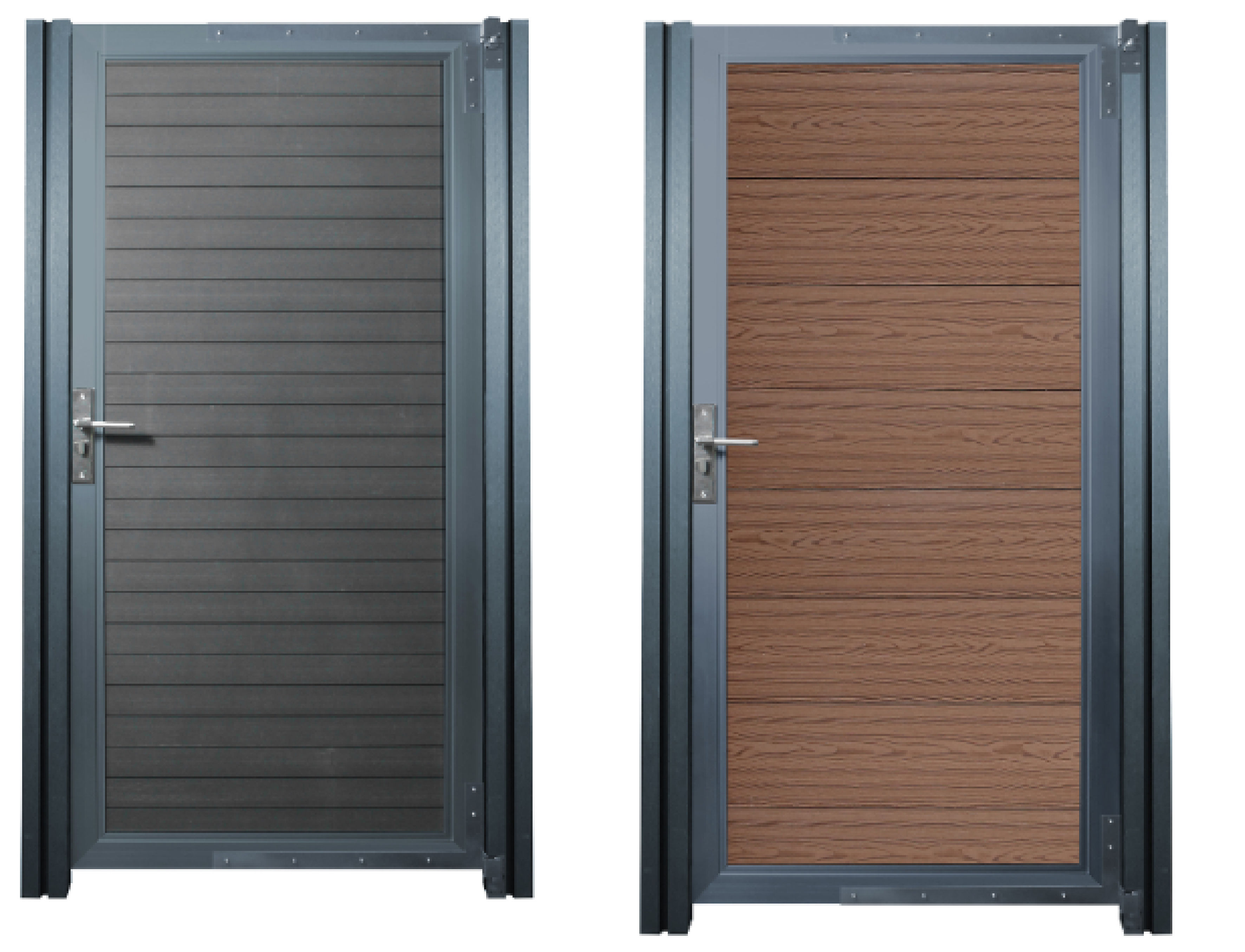
Composite panel gate – a sleek and practical solution for enhancing privacy, security, and kerb appeal.
Product Information
Composite Fencing Gates with LED Posts
Our composite garden gates combine robust construction with modern convenience, crafted from durable, low-maintenance composite materials that resist weathering and wear. Each gate includes a secure locking system for added safety and peace of mind. Designed to provide a stylish and reliable entryway, these gates feature a contemporary finish that complements any outdoor setting -making them an ideal choice for both security and curb appeal.
SKU
214902,214903
214902
Dimensions
900*1800mm
Colour
Grey
GPSR Information
UK
Manufacturer:
Monster Group UK Limited, Monster House
19-23 Alan Farnaby Way,
Industrial Estate Sheriff Hutton,
York
YO60 6PG
Person Responsible:
Rana Harvey, Monster Group UK Limited,
Monster House
19-23 Alan Farnaby Way,
Industrial Estate Sheriff Hutton,
York
YO60 6PG,
England,
+441347878880
EU
Manufacturer:
Monster Group BV,
Van Heemskerckweg 28A & B,
Venlo 5928LL
Netherlands
+441347878880
Person Responsible:
Rana Harvey,
Monster Group BV,
Van Heemskerckweg 28A & B,
Venlo 5928LL,
Netherlands,
+44134787888
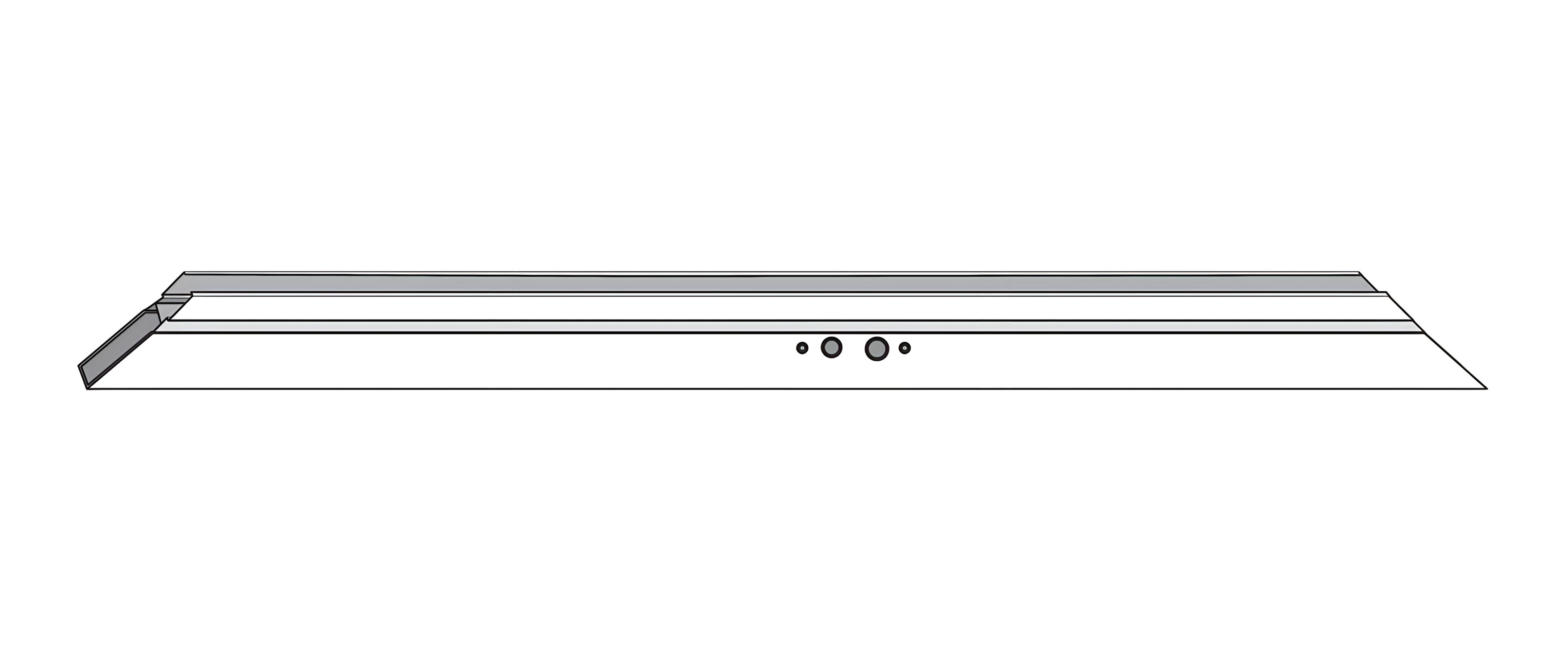
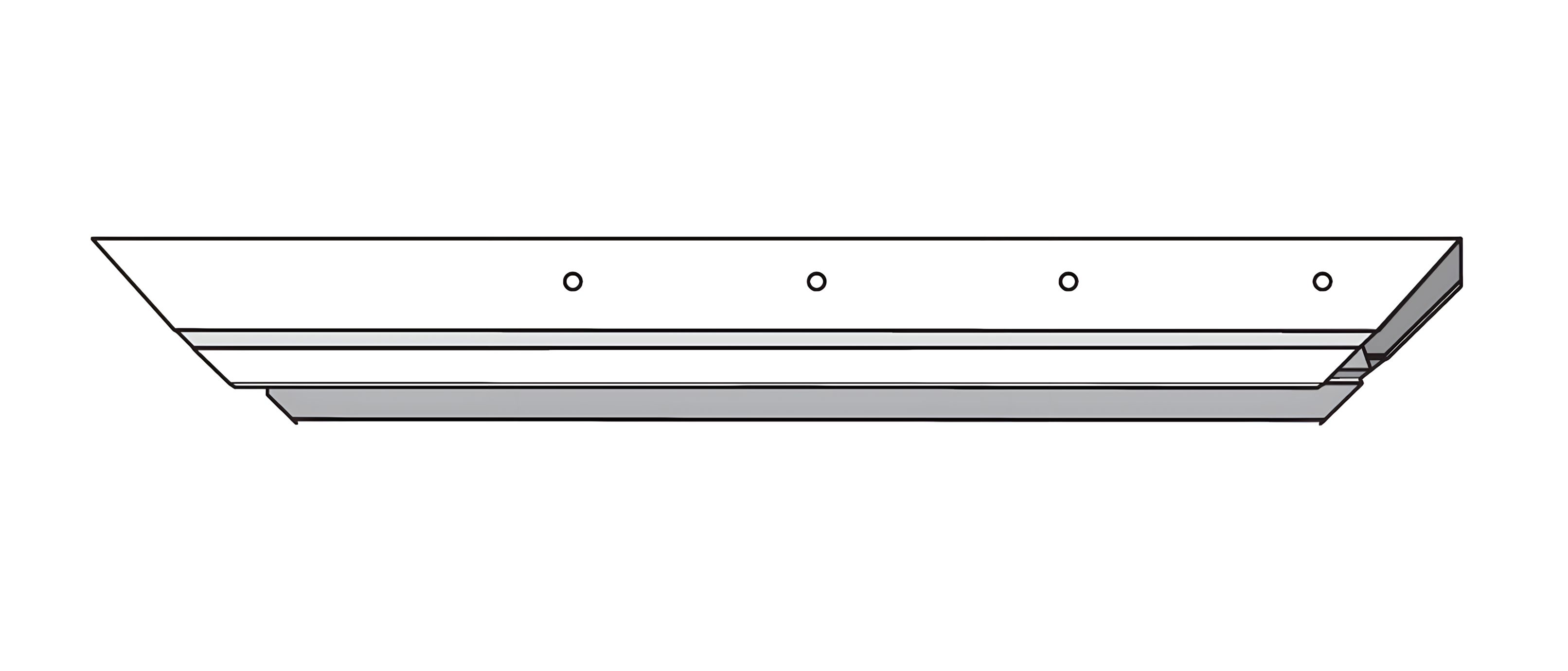
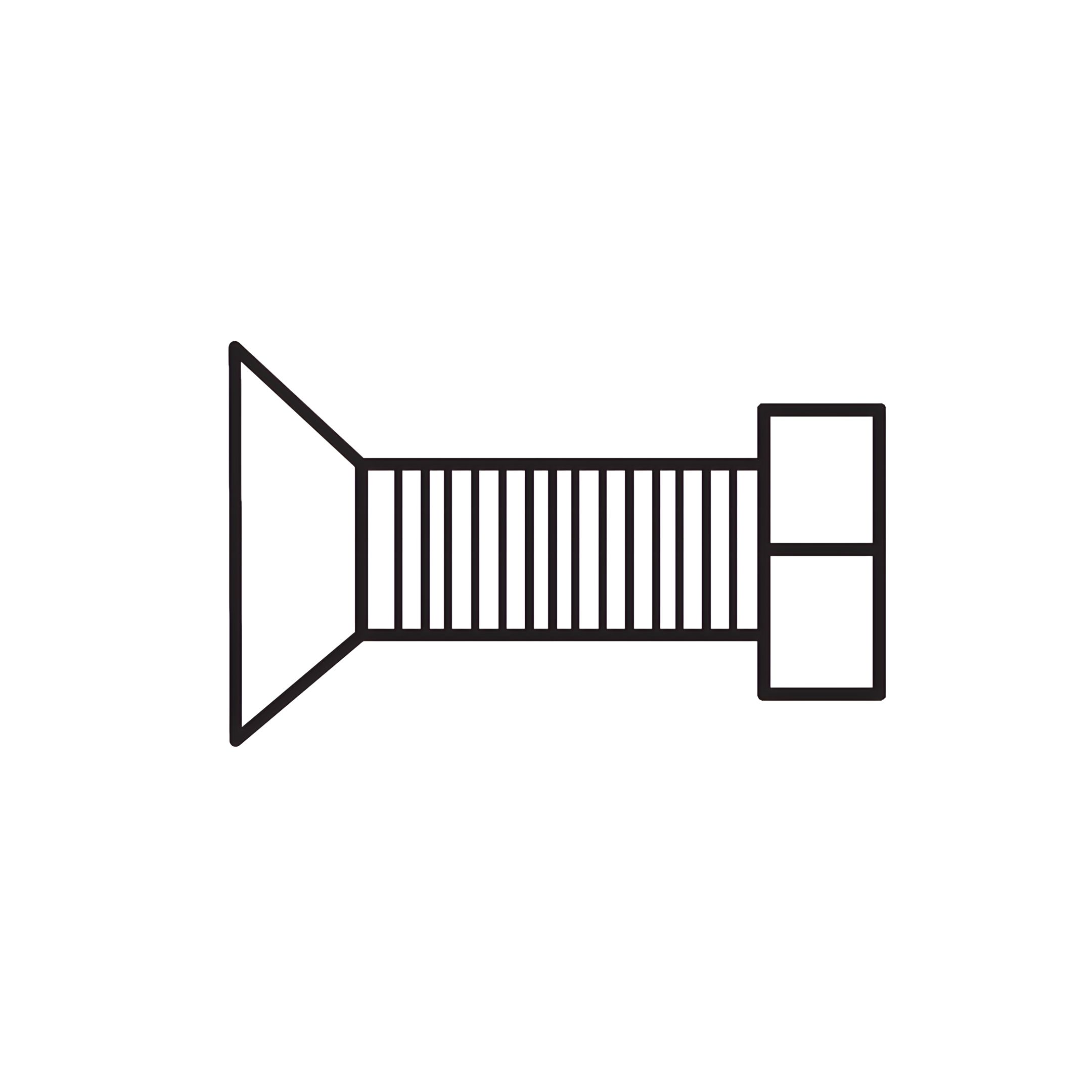
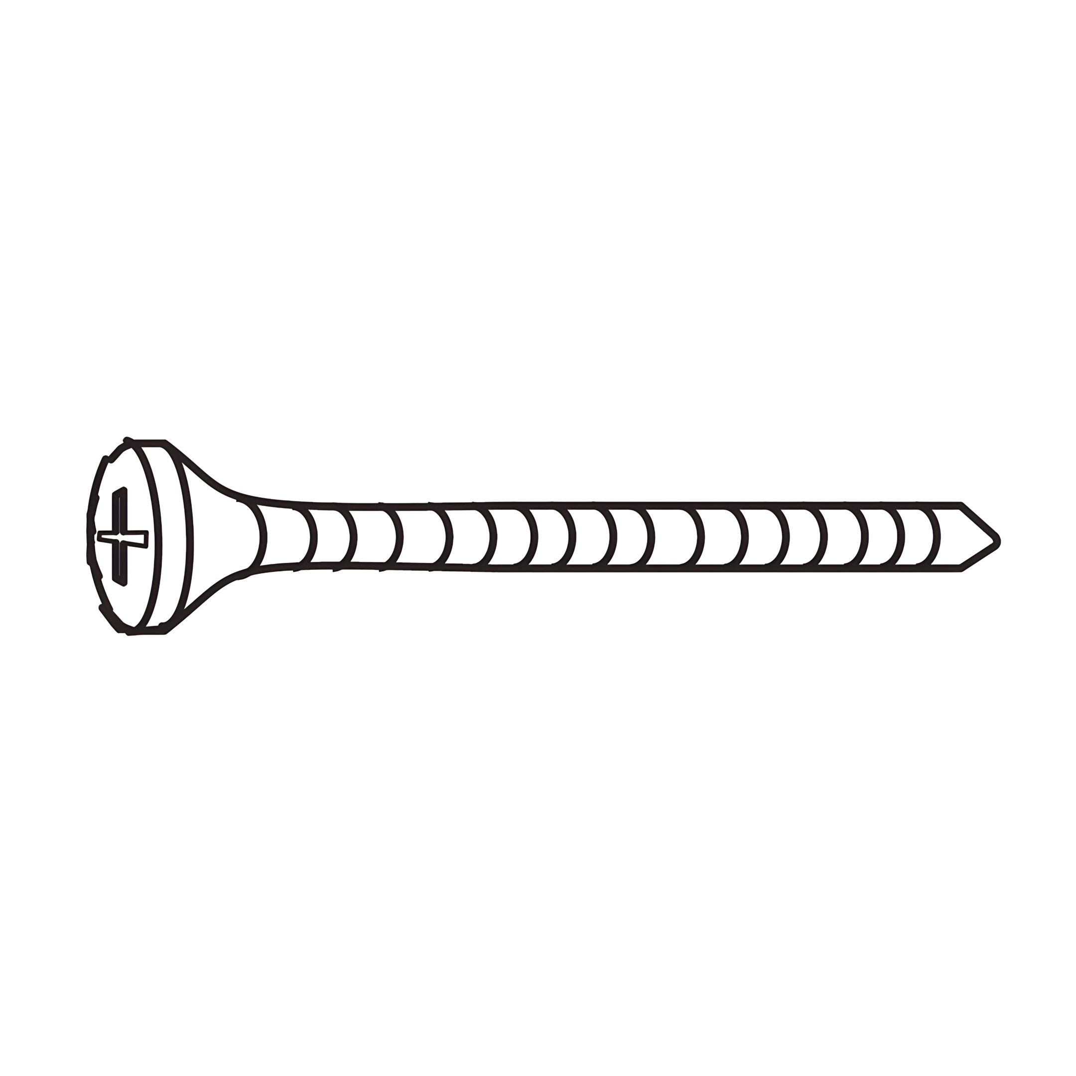
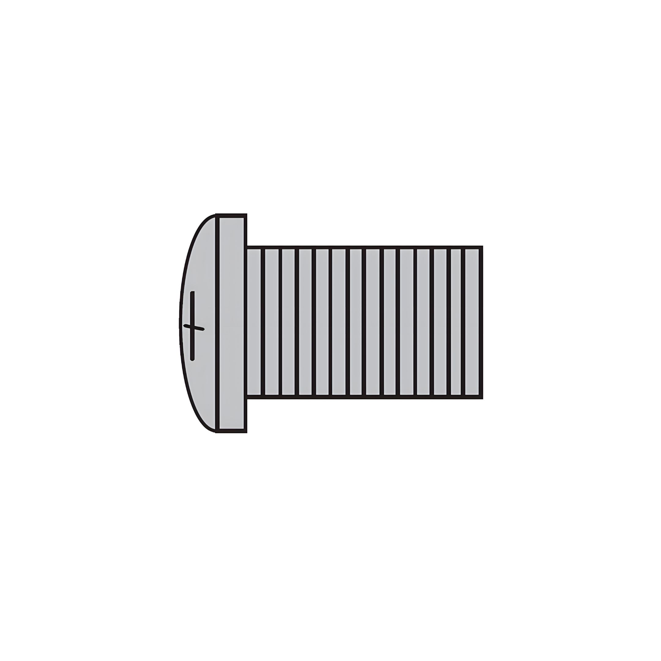
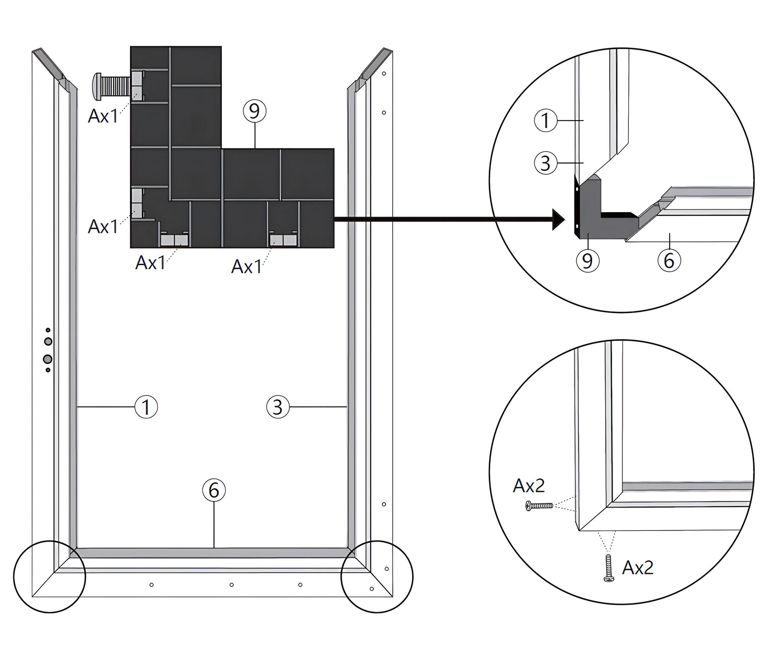
1. Position the Side Beam (Part 1) and Side Beam (Part 3) vertically. 2. Attach the Bottom Beam (Part 6) horizontally between the two side beams. 3. Use the Corner Connectors (Part 9) to secure the corners where the side beams meet the bottom beam. 4. Insert the 20mm Screws (Part A) into the designated holes on the corner connectors to secure the beams together.
Ensure all parts are aligned properly and securely fastened.
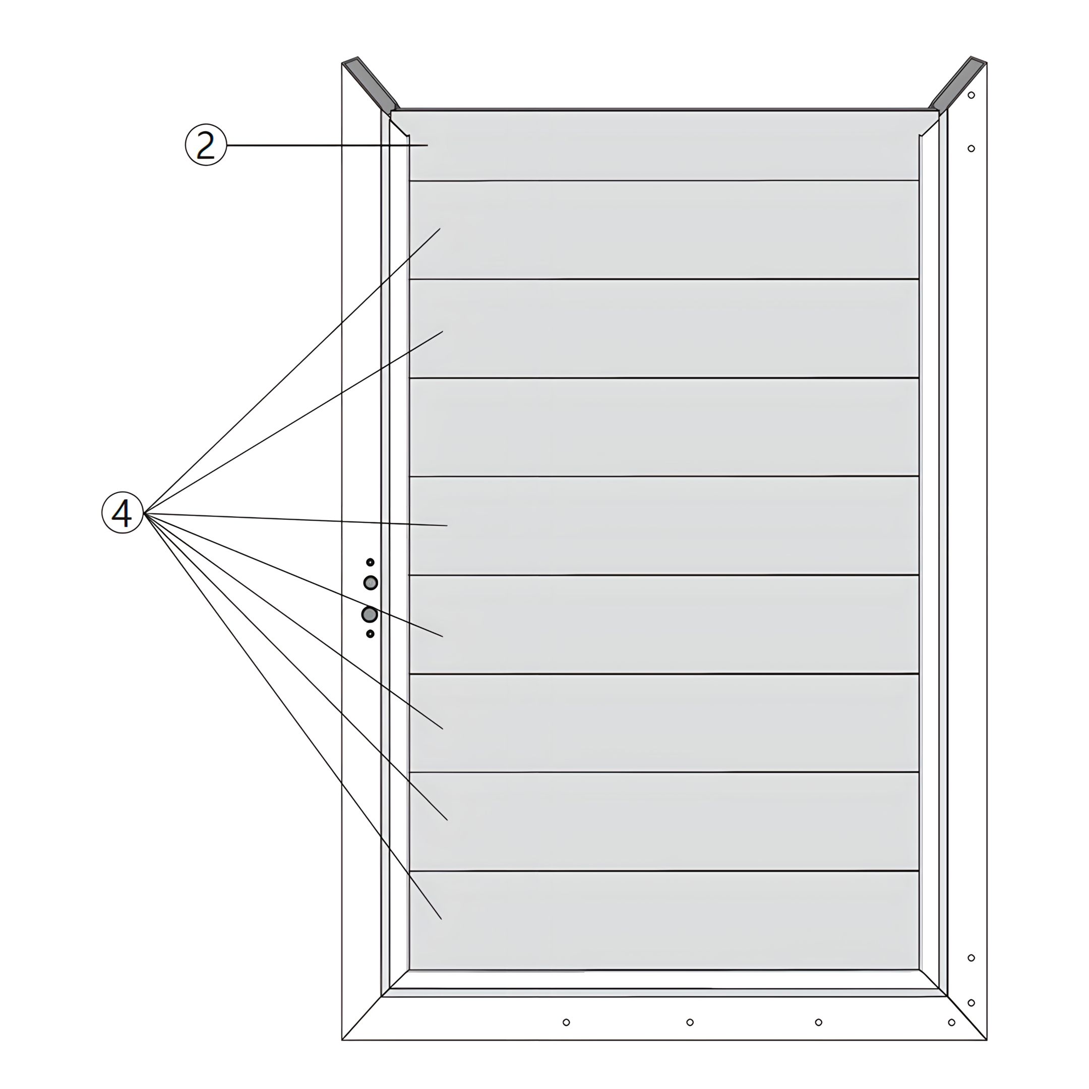
2. Gate Frame Assembly: Slat Installation
To continue assembling the gate frame, follow these steps:
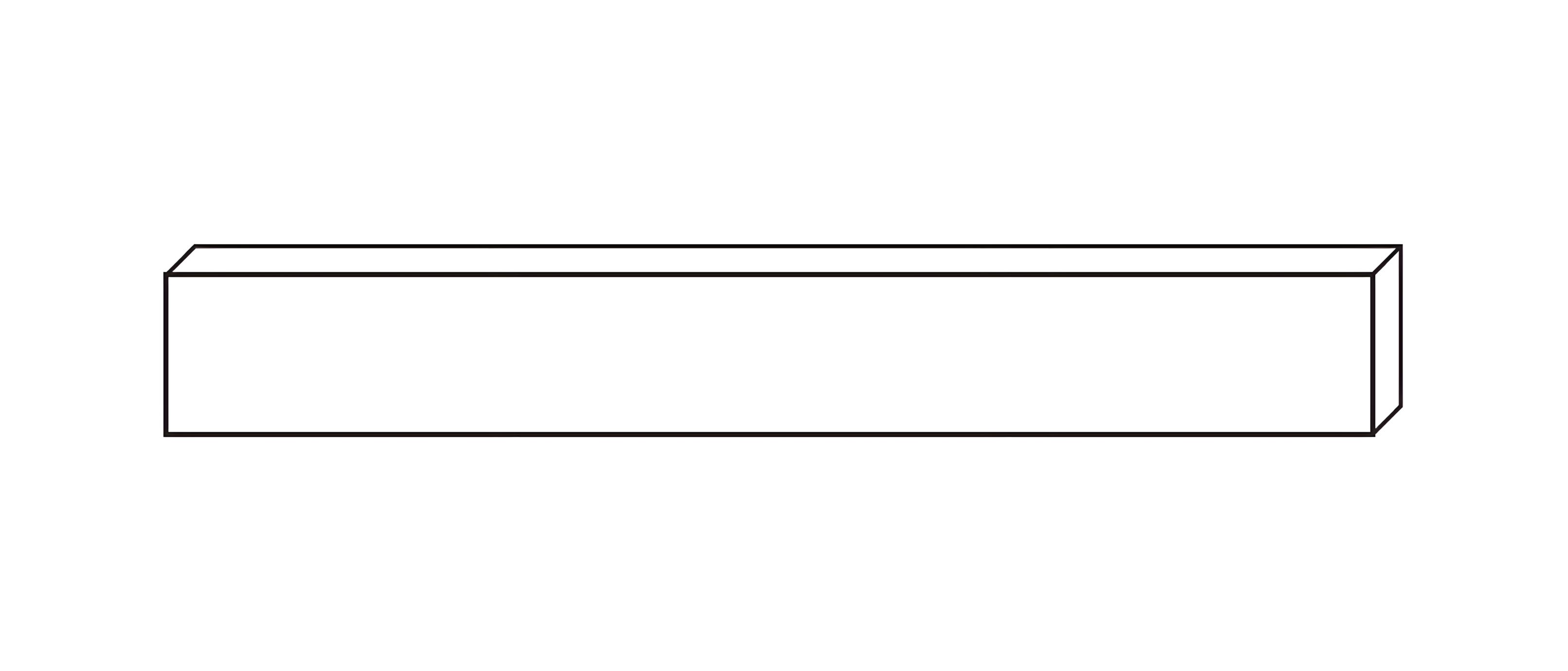
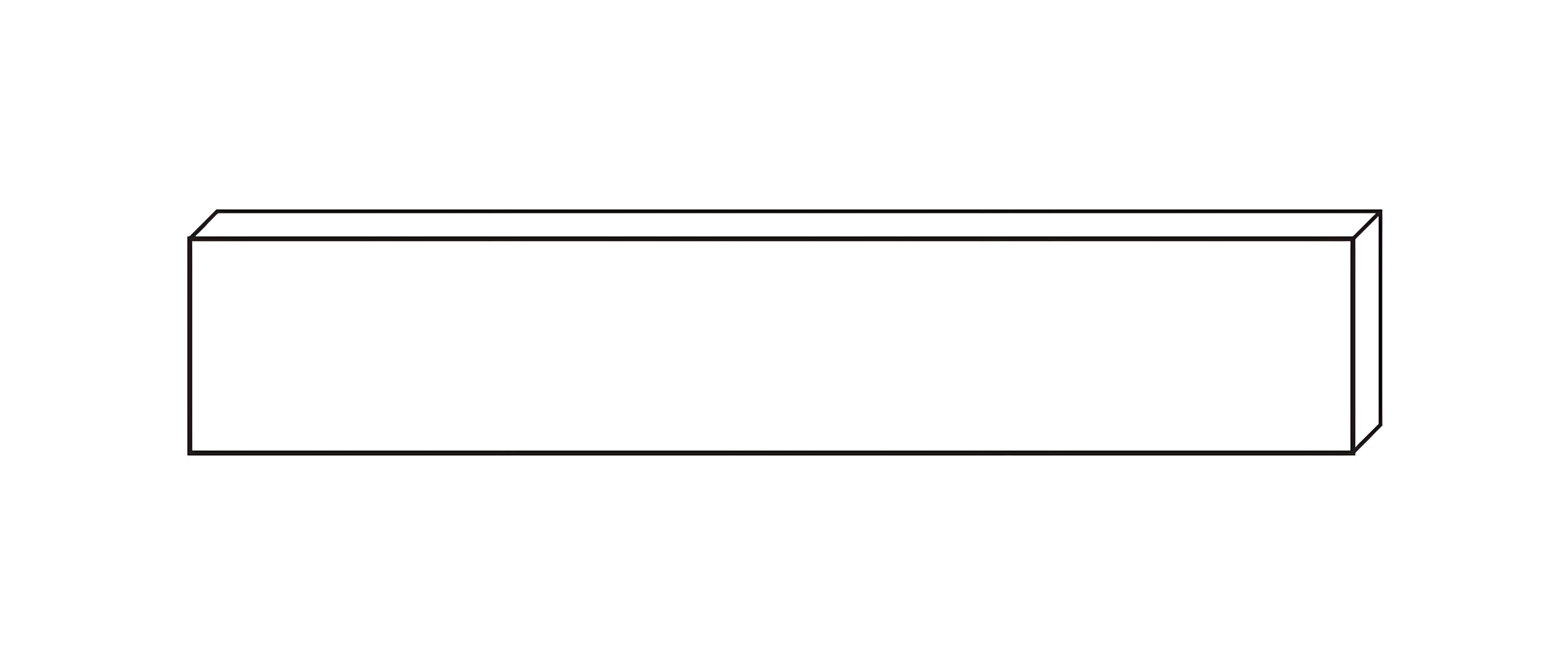
1. Insert the Gate Slats (Part 4) vertically between the side beams, ensuring they are evenly spaced and aligned. 2. Position the Top Gate Slat (Part 2) horizontally at the top of the frame.
Ensure all components are properly aligned and securely fastened to maintain the structural integrity of the gate.
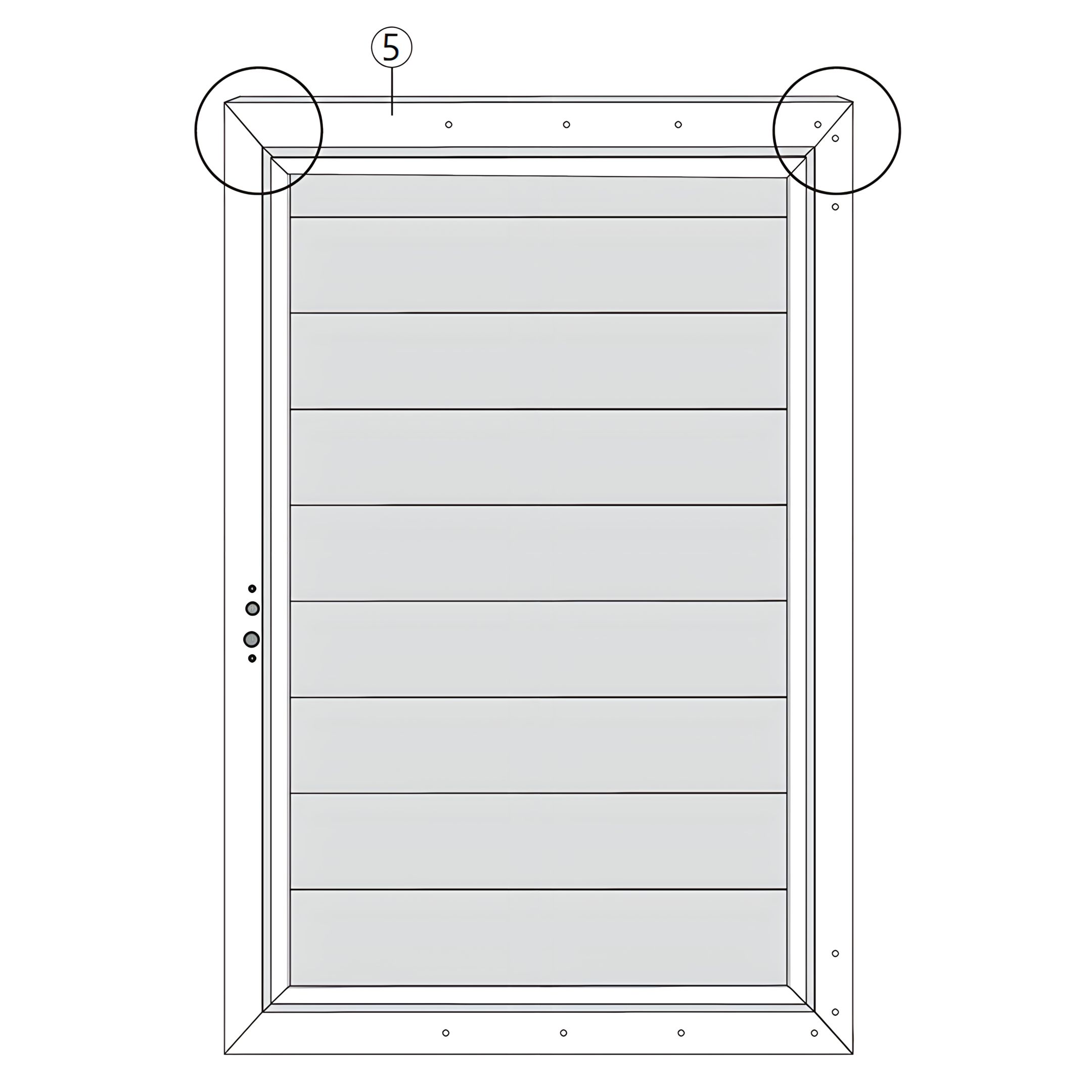
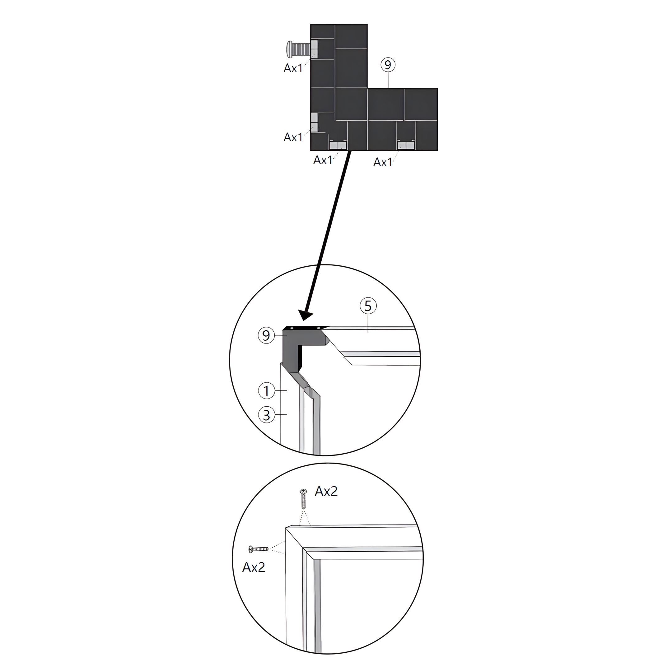
3. Gate Frame Assembly Alignment
To complete the gate frame assembly, follow these steps:
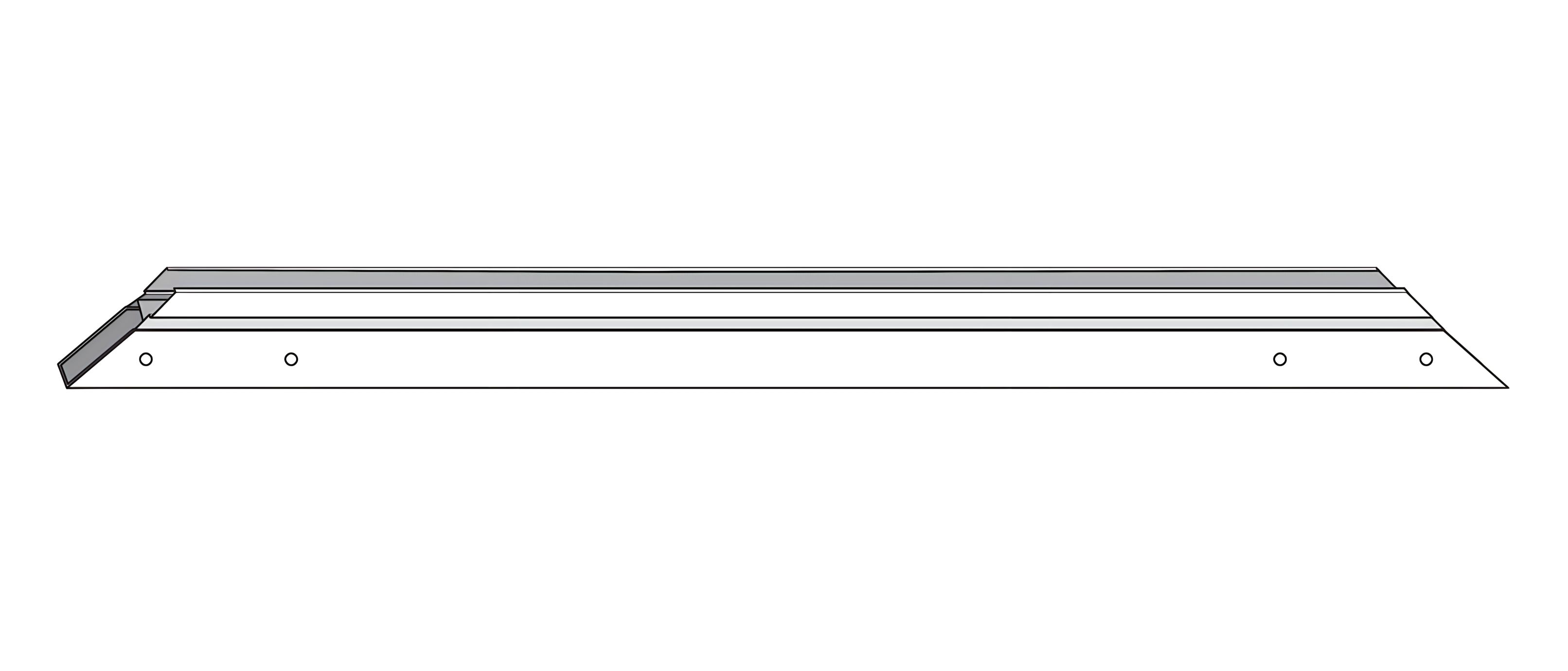
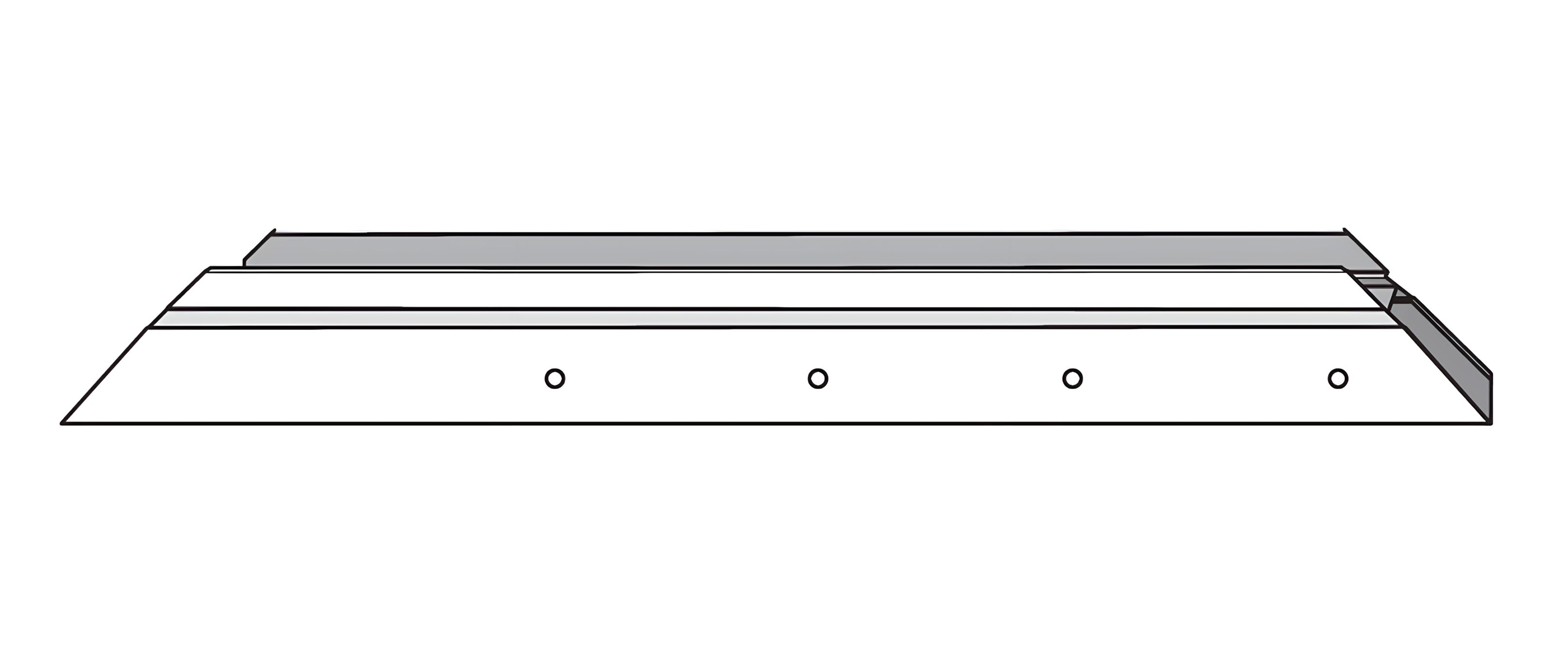
1. Position the Top Beam (Part 5) horizontally at the top of the frame. 2. Use the Corner Connectors (Part 9) to secure the corners where the top beam meets the side beams (Parts 1 and 3). 3. Insert the 20mm Screws (Part A) into the designated holes on the corner connectors to secure the beams together.
Ensure all parts are aligned properly and securely fastened to maintain the structural integrity of the gate.
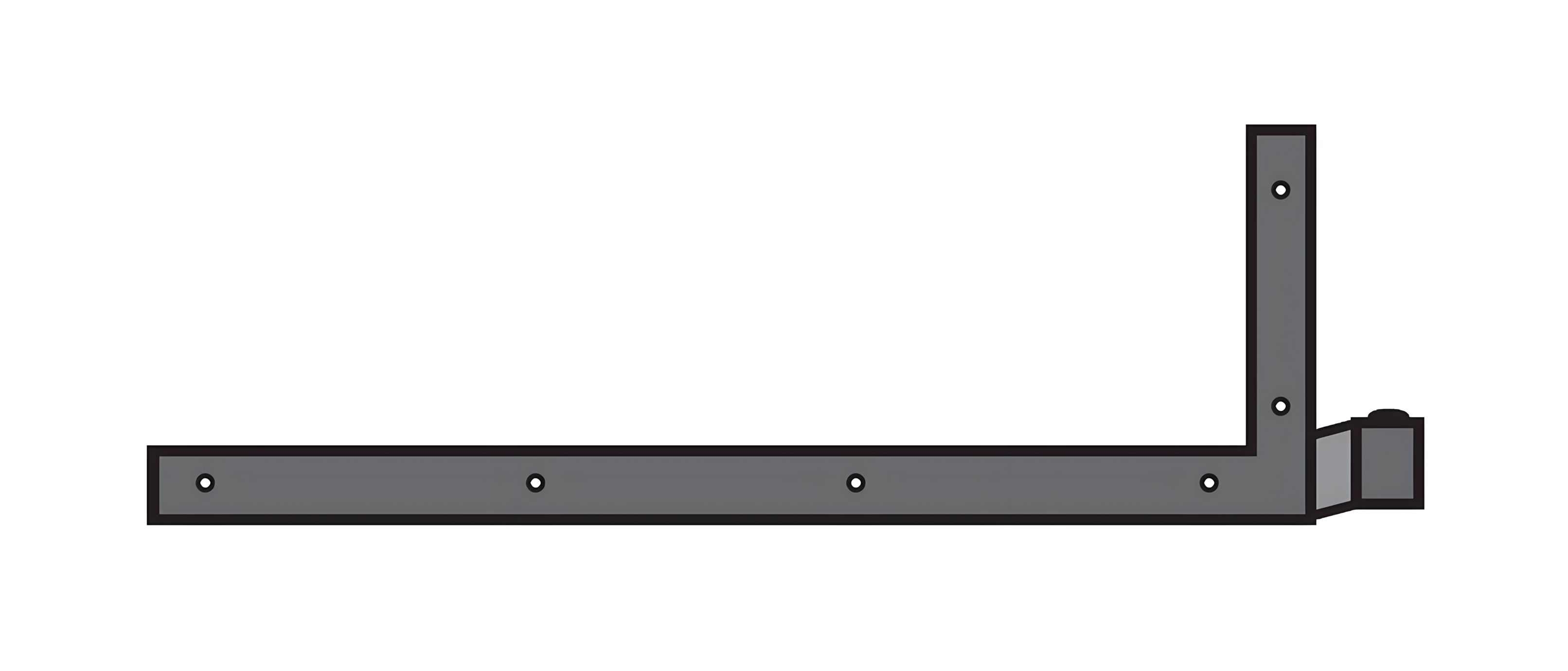
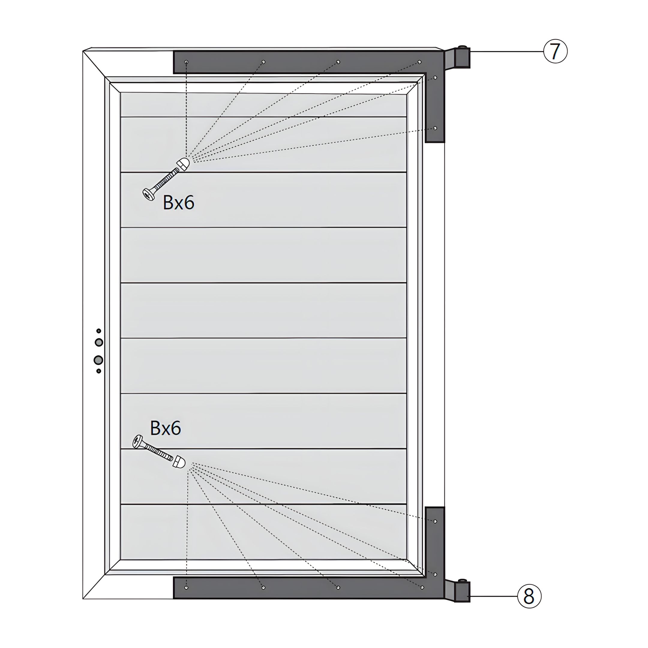
4. Gate Hinge Installation
To install the hinges on the gate, follow these steps:
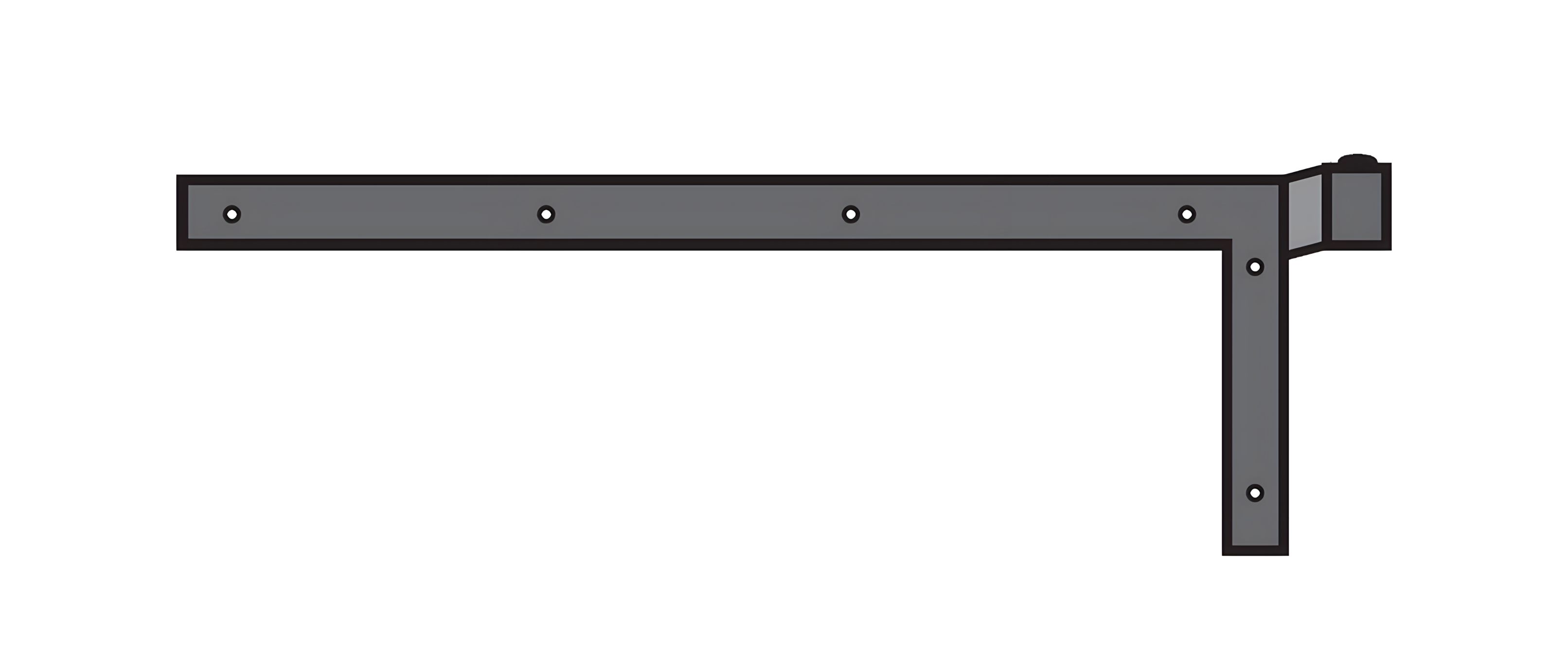
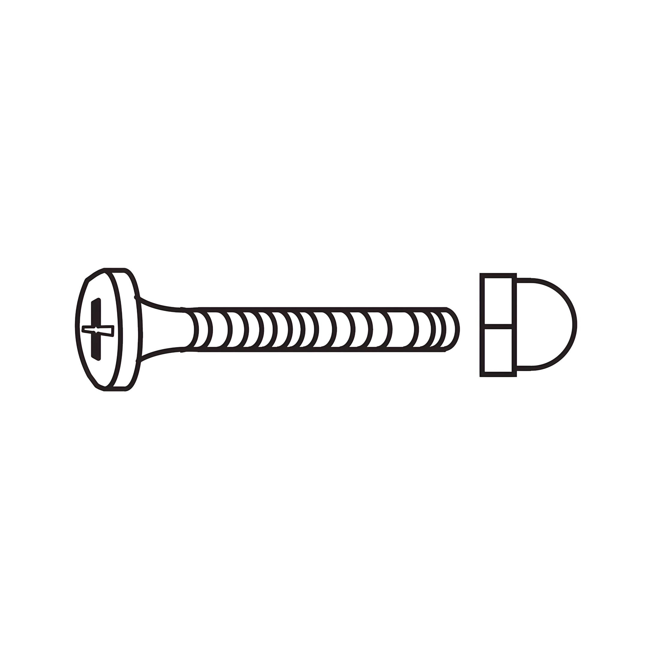
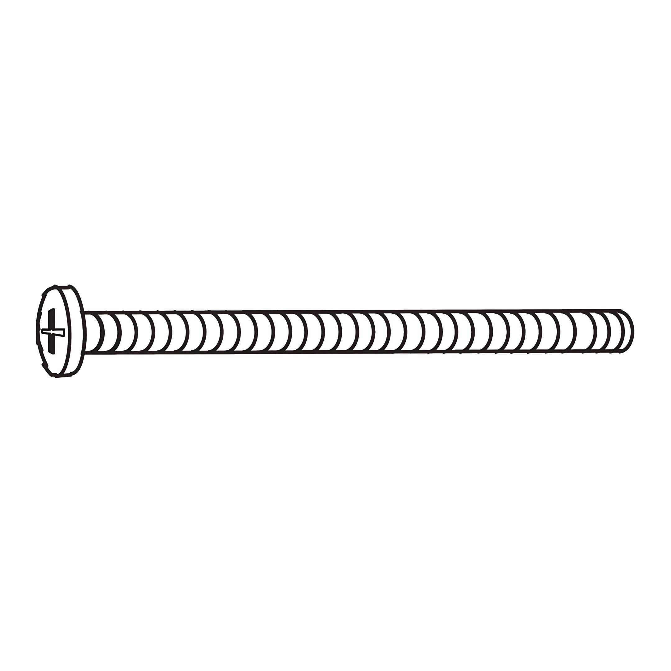
1. Position the Top Hinge (Part 7) at the top corner of the gate frame. 2. Secure the top hinge using 45mm Screws (Part B), ensuring it is firmly attached. 3. Position the Bottom Hinge (Part 8) at the bottom corner of the gate frame. 4. Secure the bottom hinge using 45mm Screws (Part B), ensuring it is firmly attached.
Ensure both hinges are aligned properly to allow smooth operation of the gate.
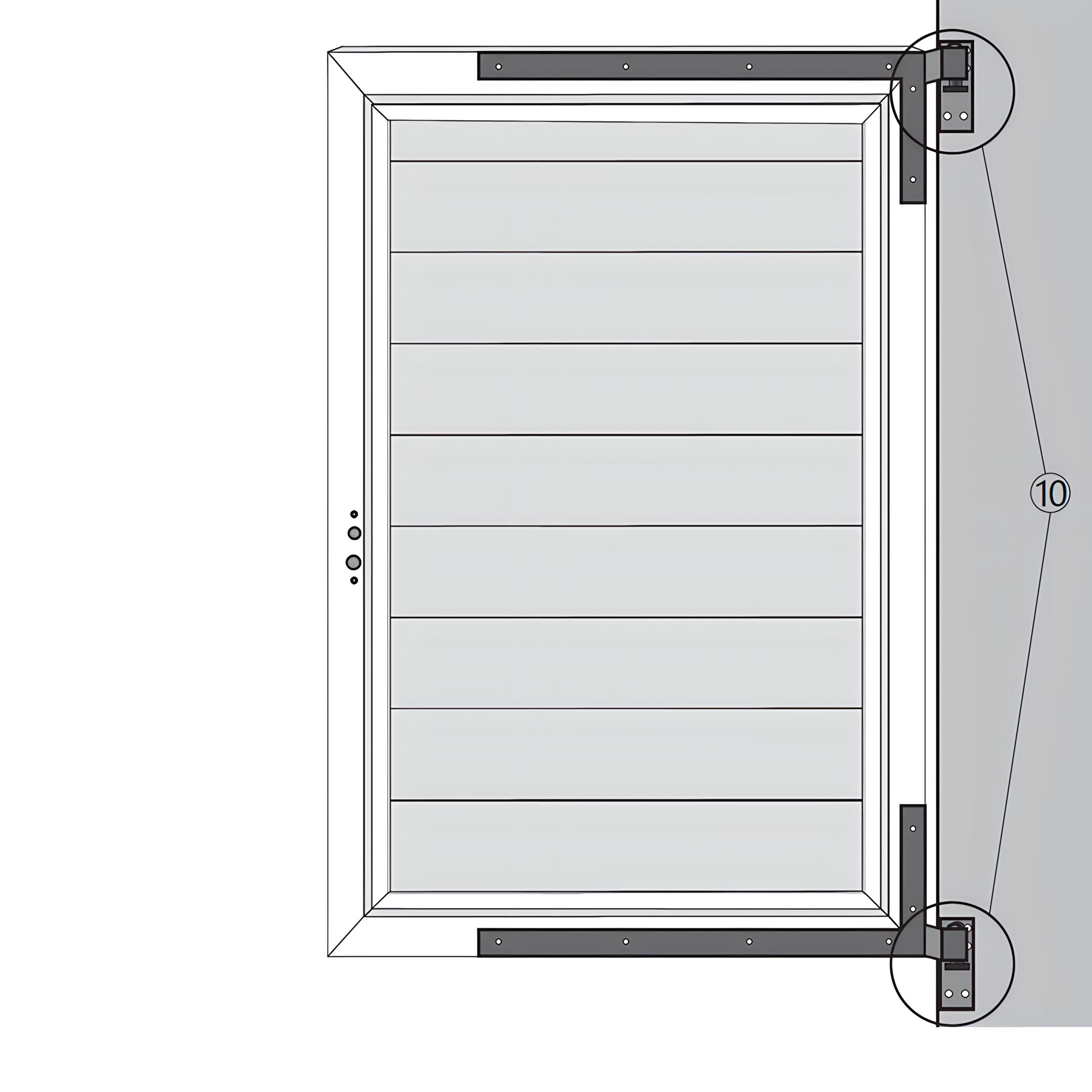
5. Gate Fittings Installation and Alignment
To install the gate securing fittings, follow these steps:
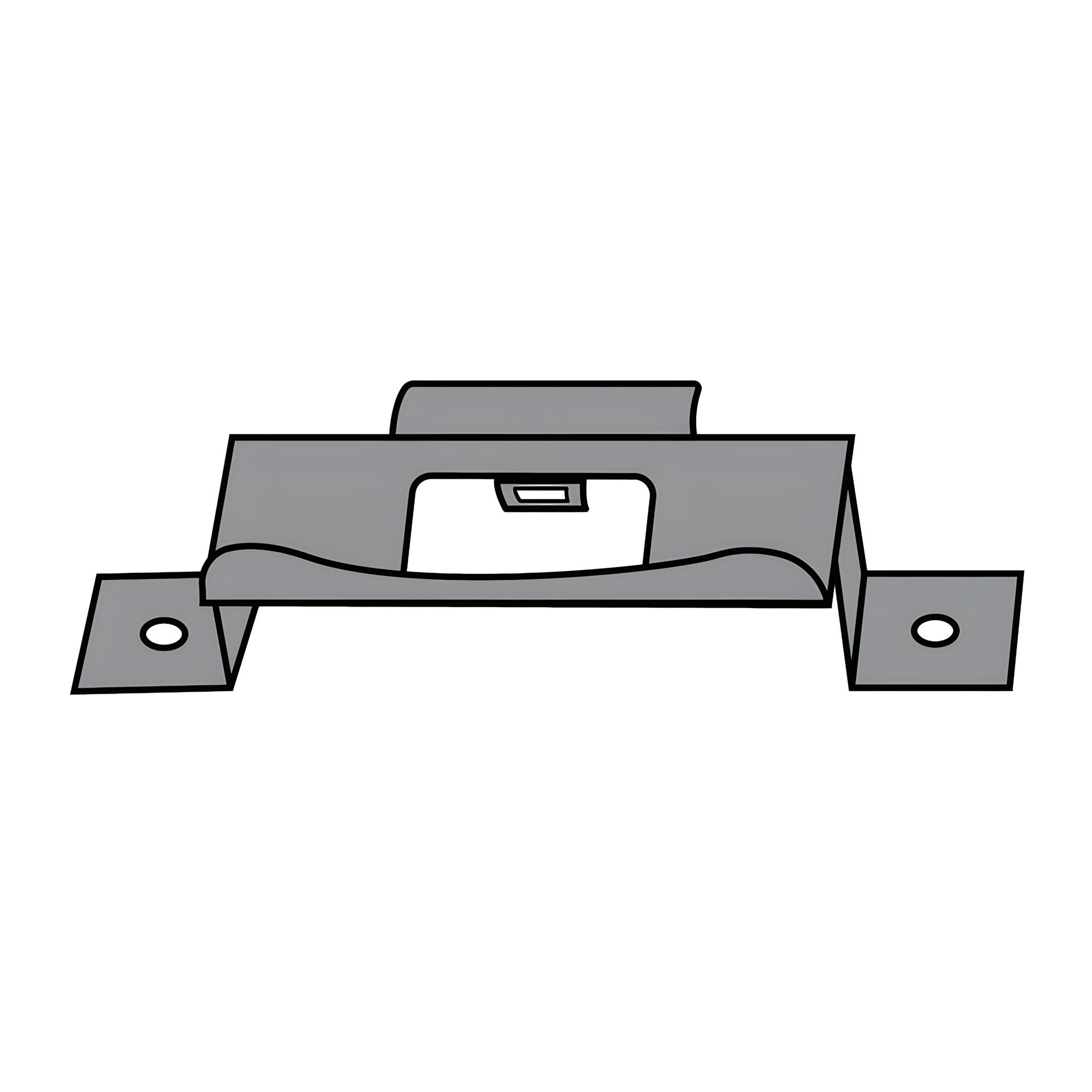
1. Position the Gate Securing Fittings (Part 10) at the top and bottom corners of the gate frame and secure to the LED Aluminium Posts. 2. Ensure the fittings are aligned with the hinges for proper operation. 3. Secure the fittings using the appropriate screws, ensuring they are firmly attached.
Ensure all components are properly aligned and securely fastened to maintain the structural integrity and functionality of the gate.
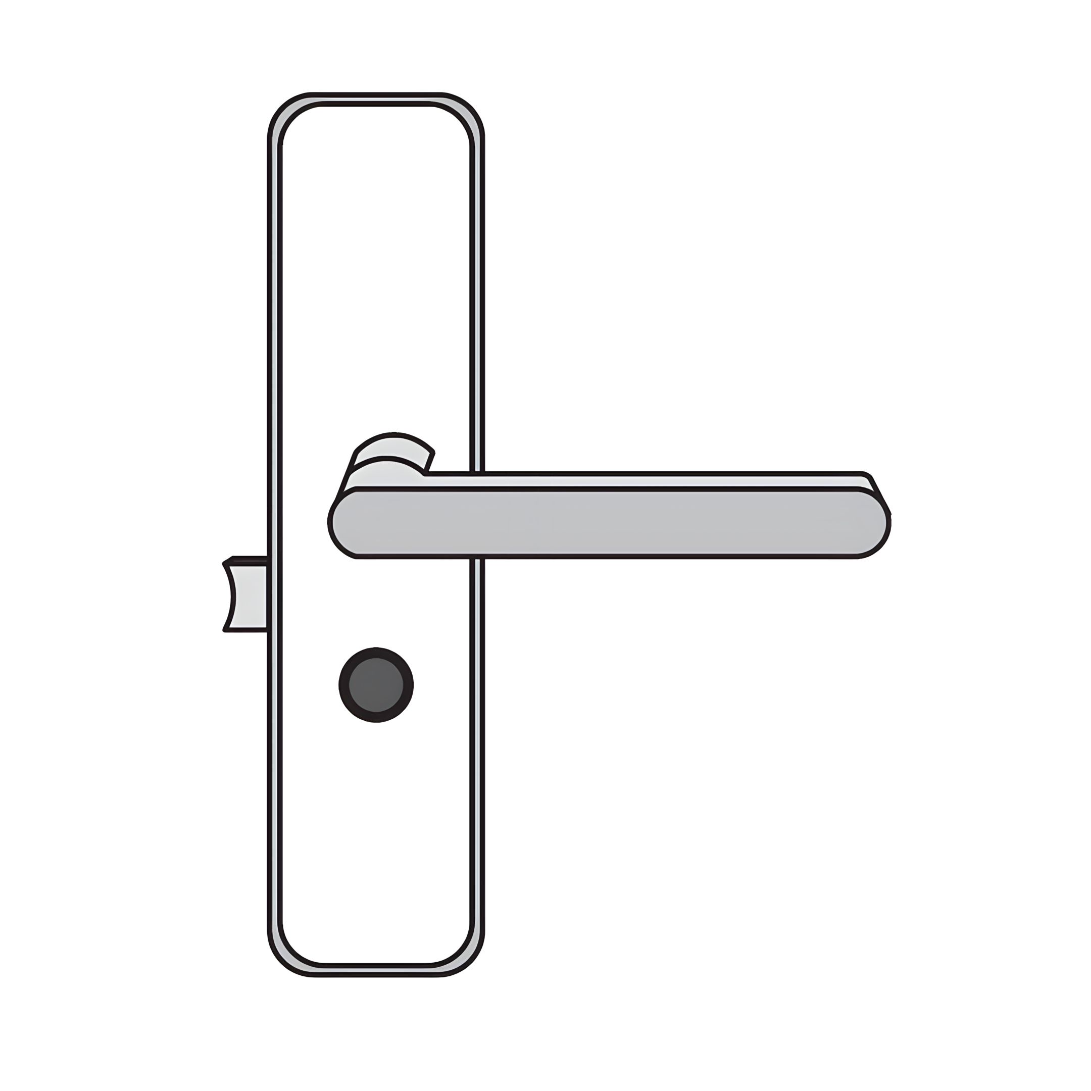
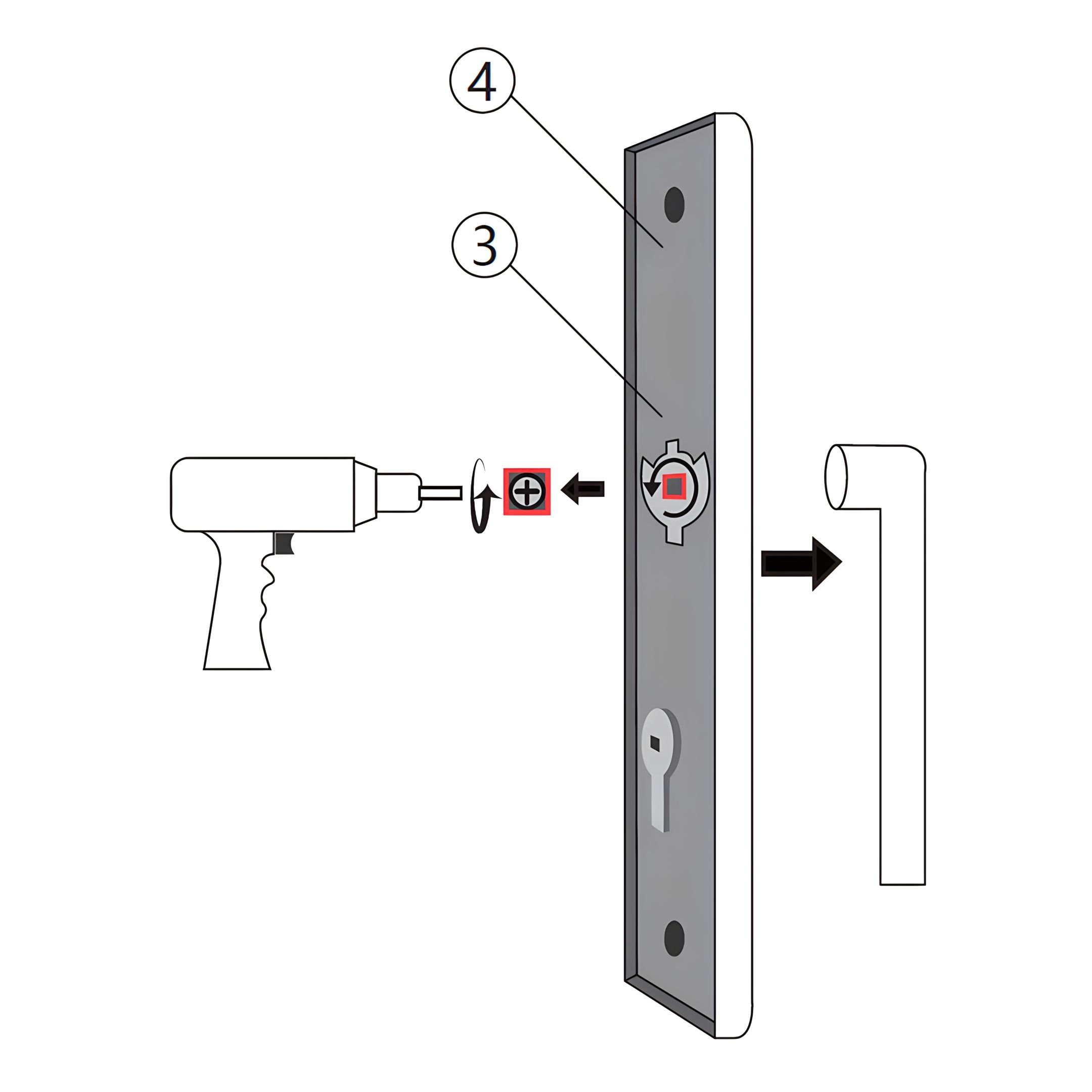
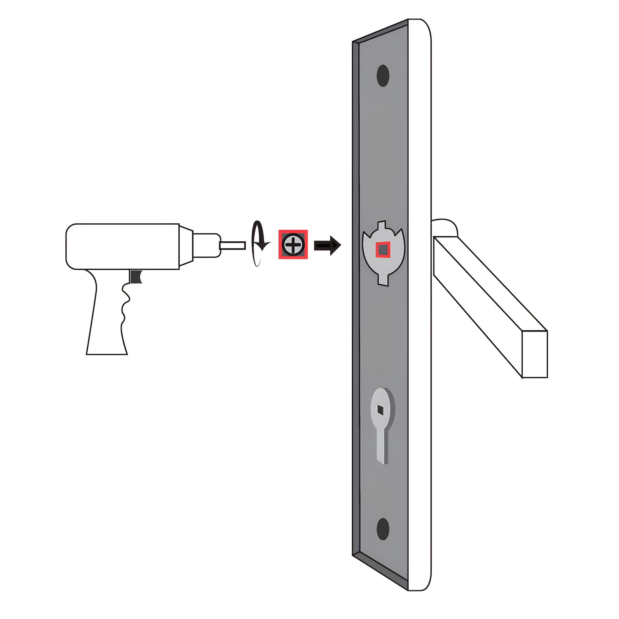
6. Gate Lock Handle Installation
To install the lock handle on the gate, follow these steps:
1. Secure the handles using the a drill, ensuring it is firmly attached to the panel it is being fixed to.
Ensure the lock handle is properly aligned for smooth operation.
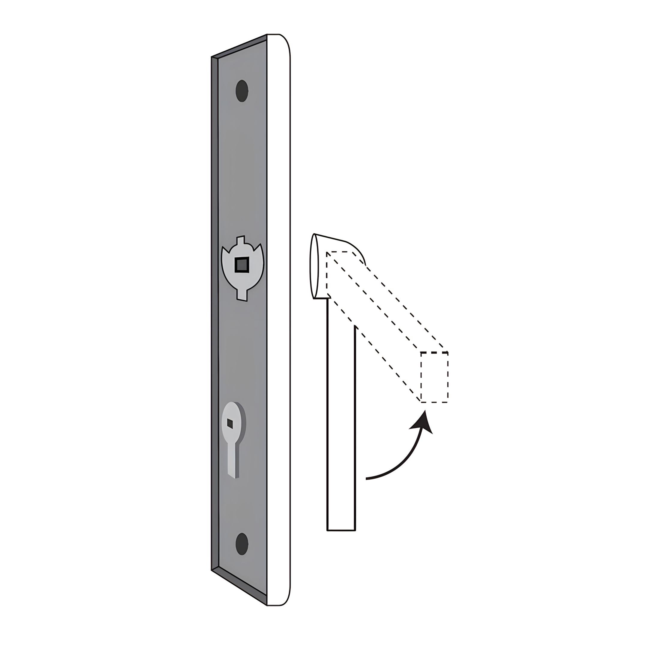
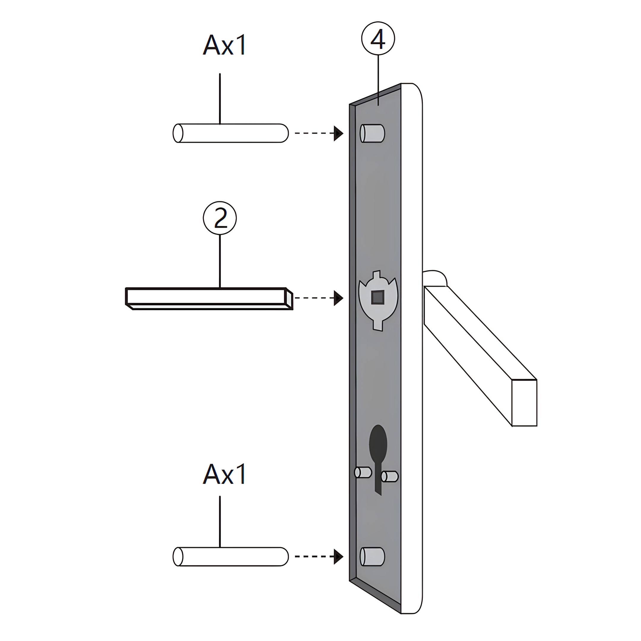
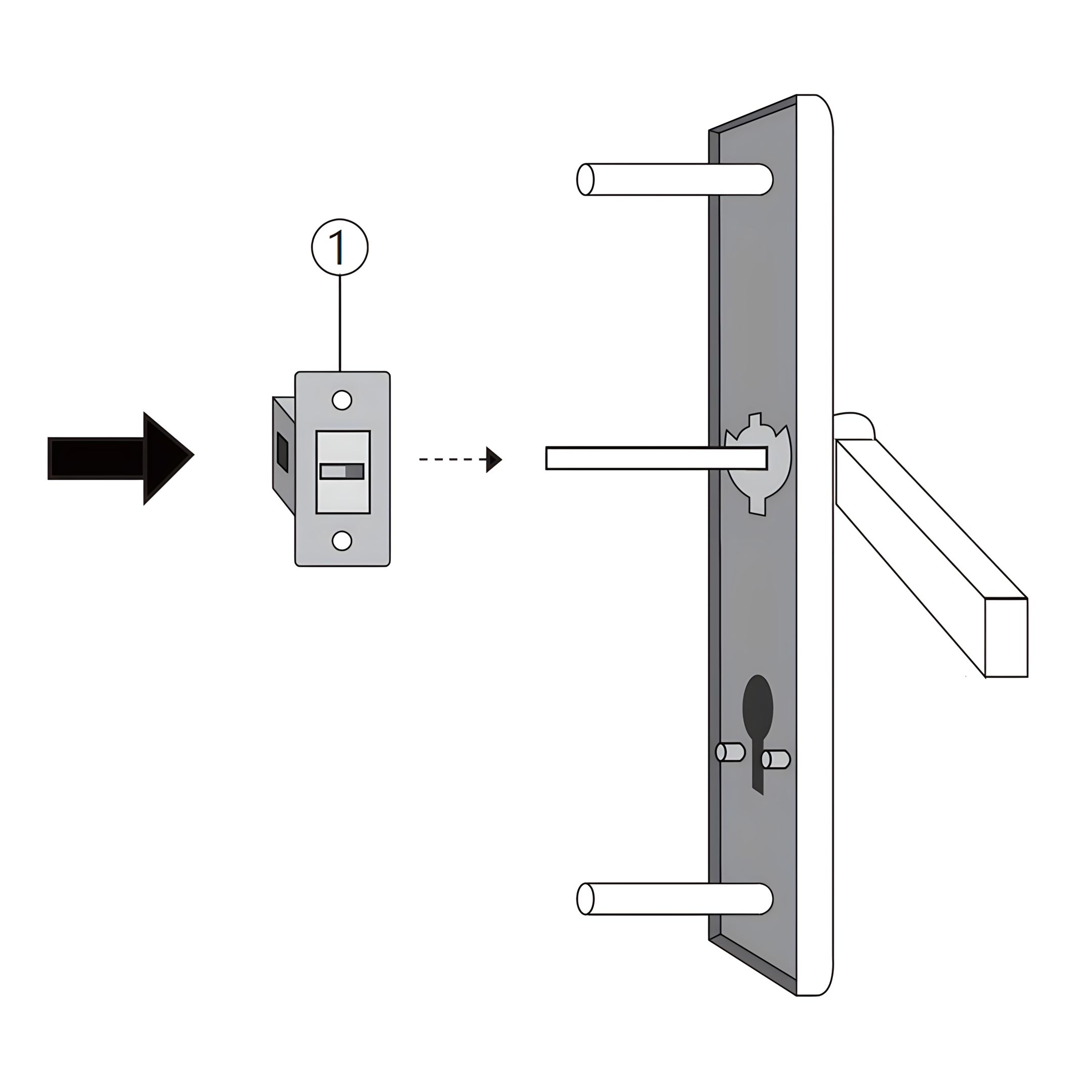
7. Lock Mechanism Assembly
To install the lock mechanism on the gate, follow these steps:
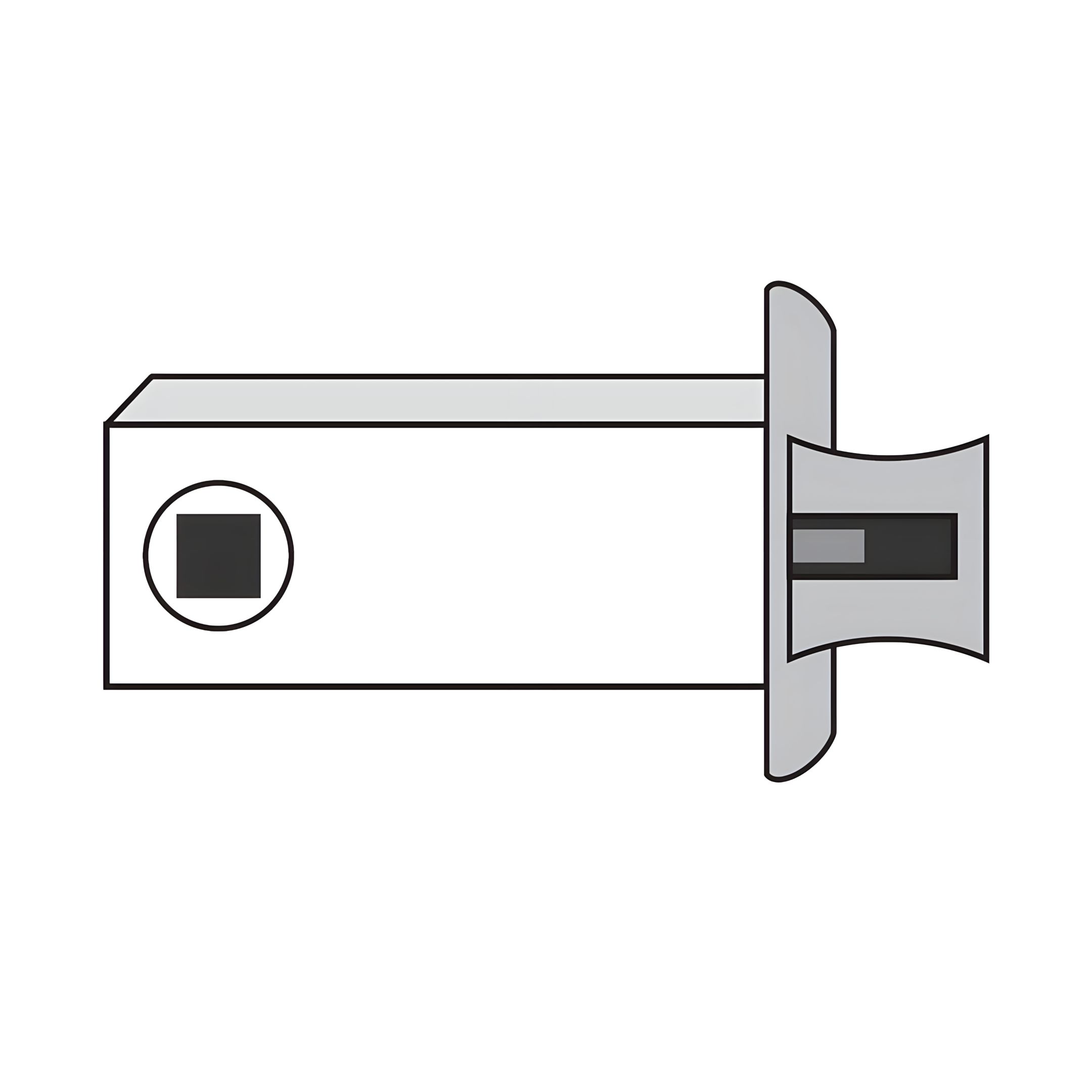
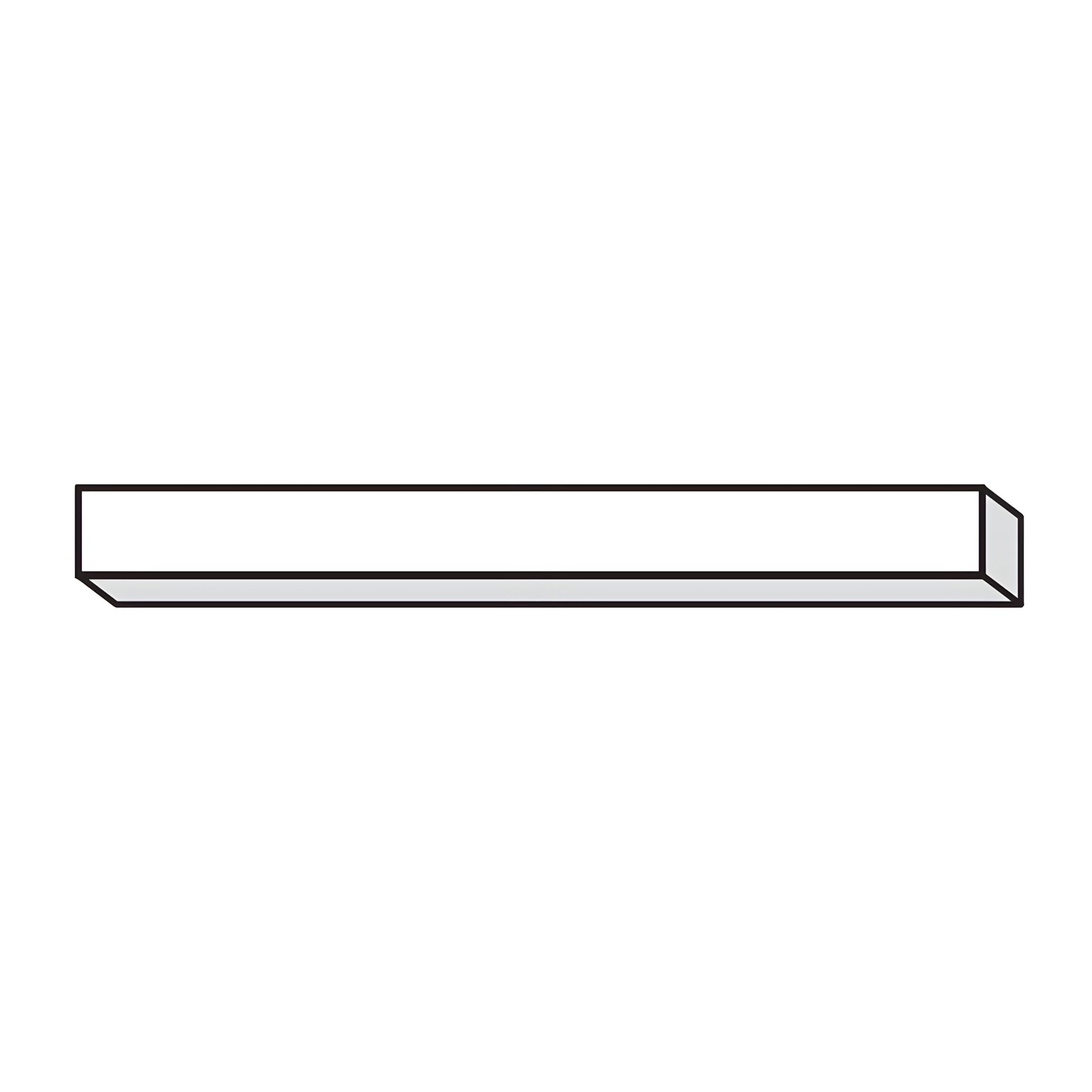
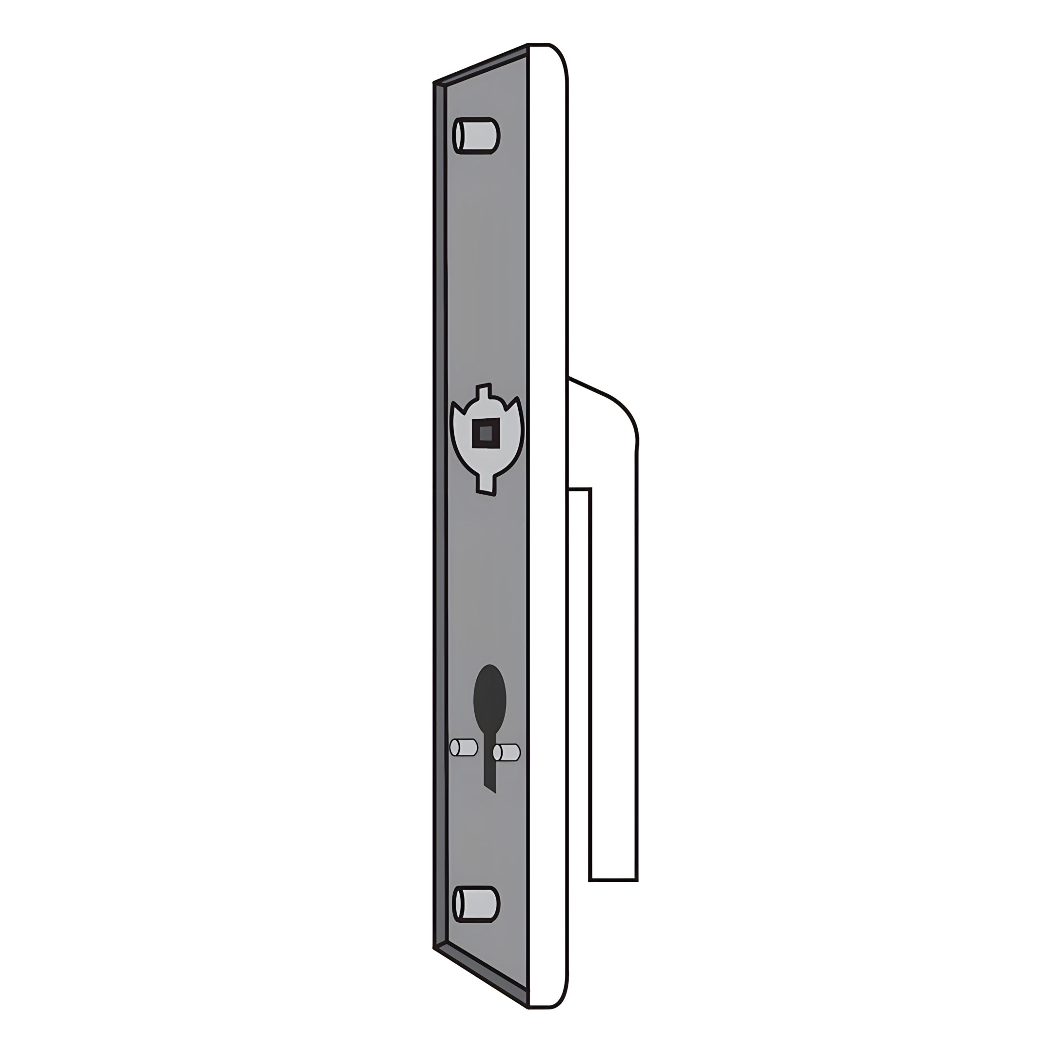
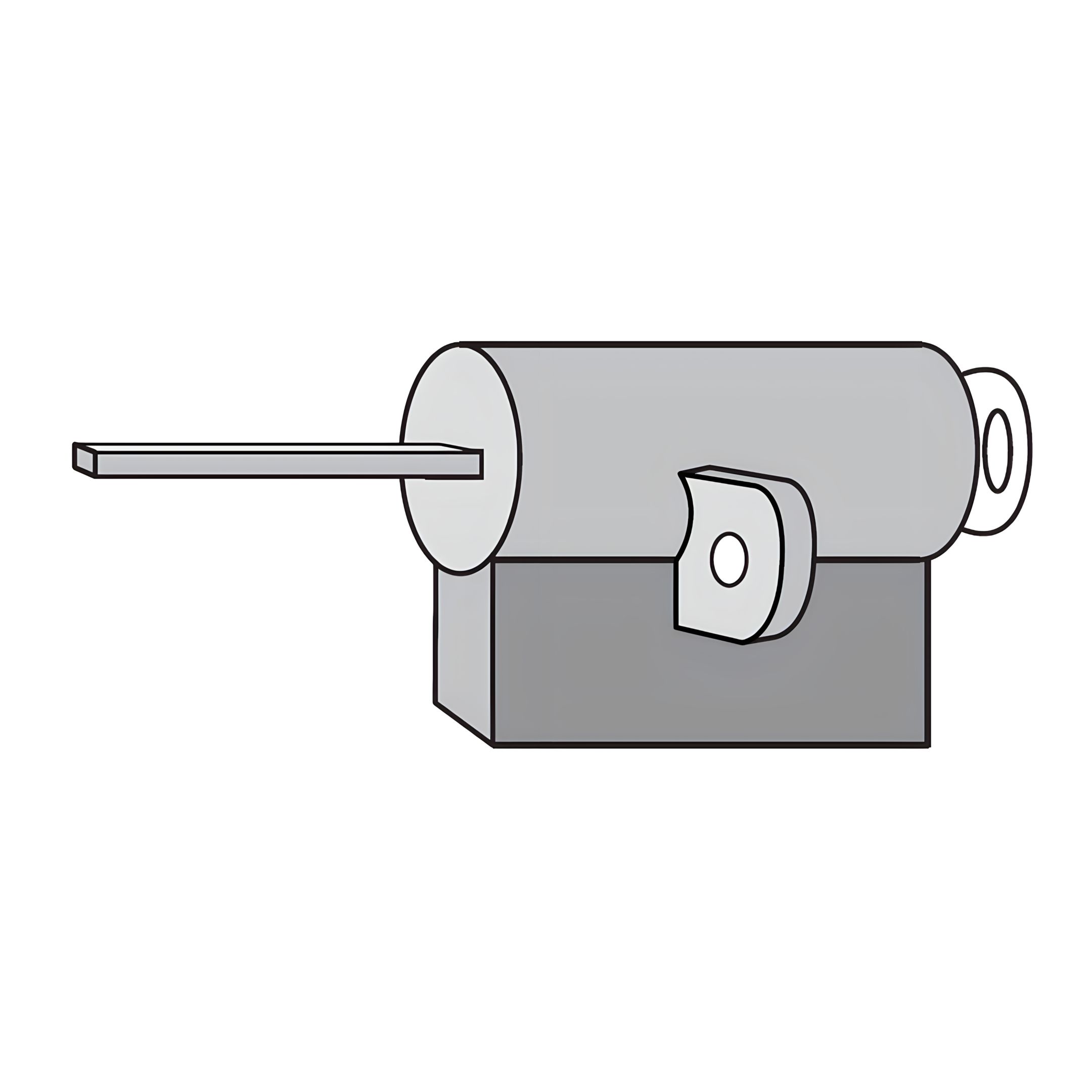
1. Insert the Connecting Rod (Lock Part A) through the designated holes on the Lock Handle Back Panel (Lock Part 4). 2. Align and insert the Latch Connecting Bar (Lock Part 2) into the corresponding slot on the back handle. 3. Position the Handle Mechanism (Lock Part 1) onto the connecting rods and latch bar, ensuring proper alignment.
Ensure all components are securely connected and aligned for proper lock functionality.
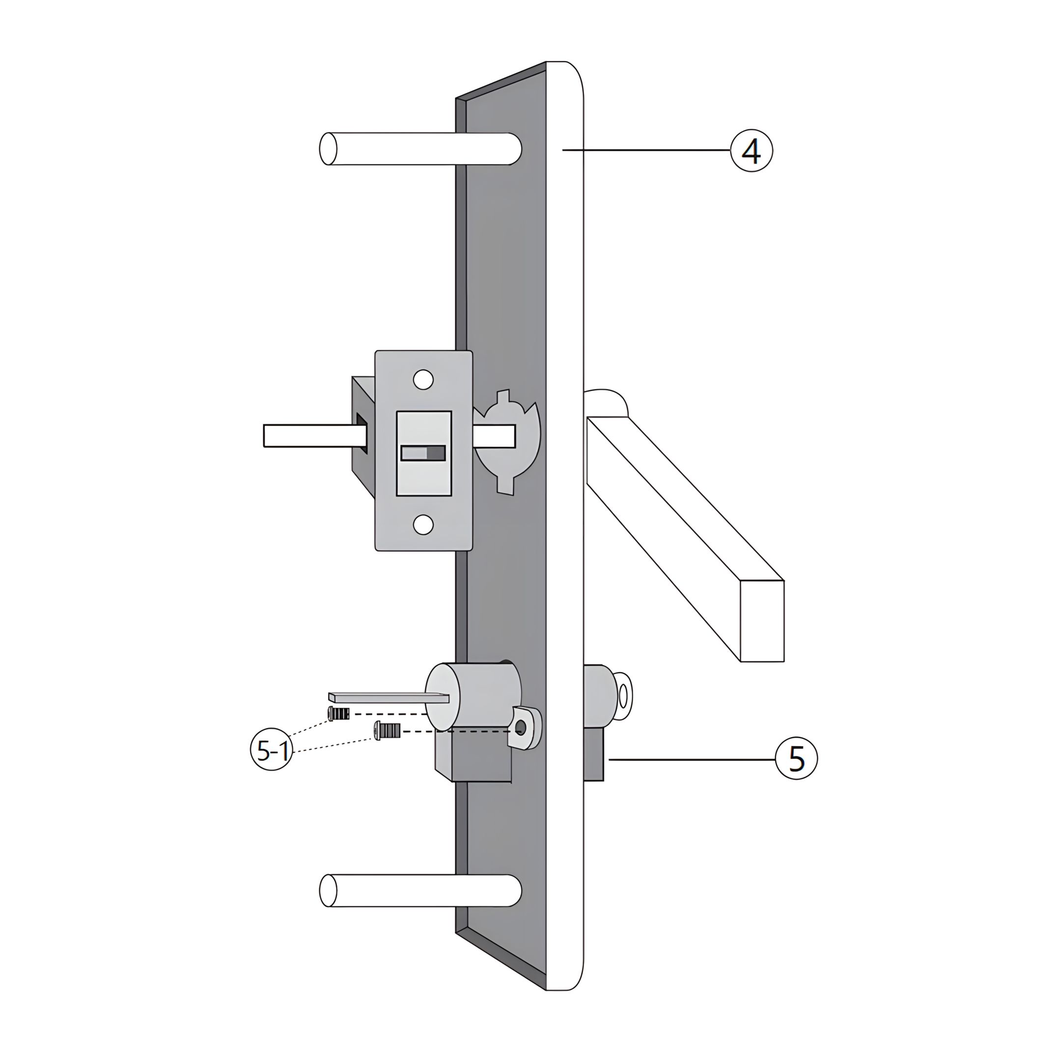
8. "Key Mechanism Installation for Gate Lock"
To complete the lock mechanism installation on the gate, follow these steps:
1. Position the Key Mechanism (Lock Part 5) into the designated slot on the Lock Handle Back Panel (Lock Part 4). 2. Secure the key mechanism using the Key Mechanism Screws (Lock Part 5-1), ensuring it is firmly attached.
Ensure all components are securely connected and aligned for proper lock functionality.
9. Lock Mechanism Assembly
To complete the lock mechanism installation on the gate, follow these steps:
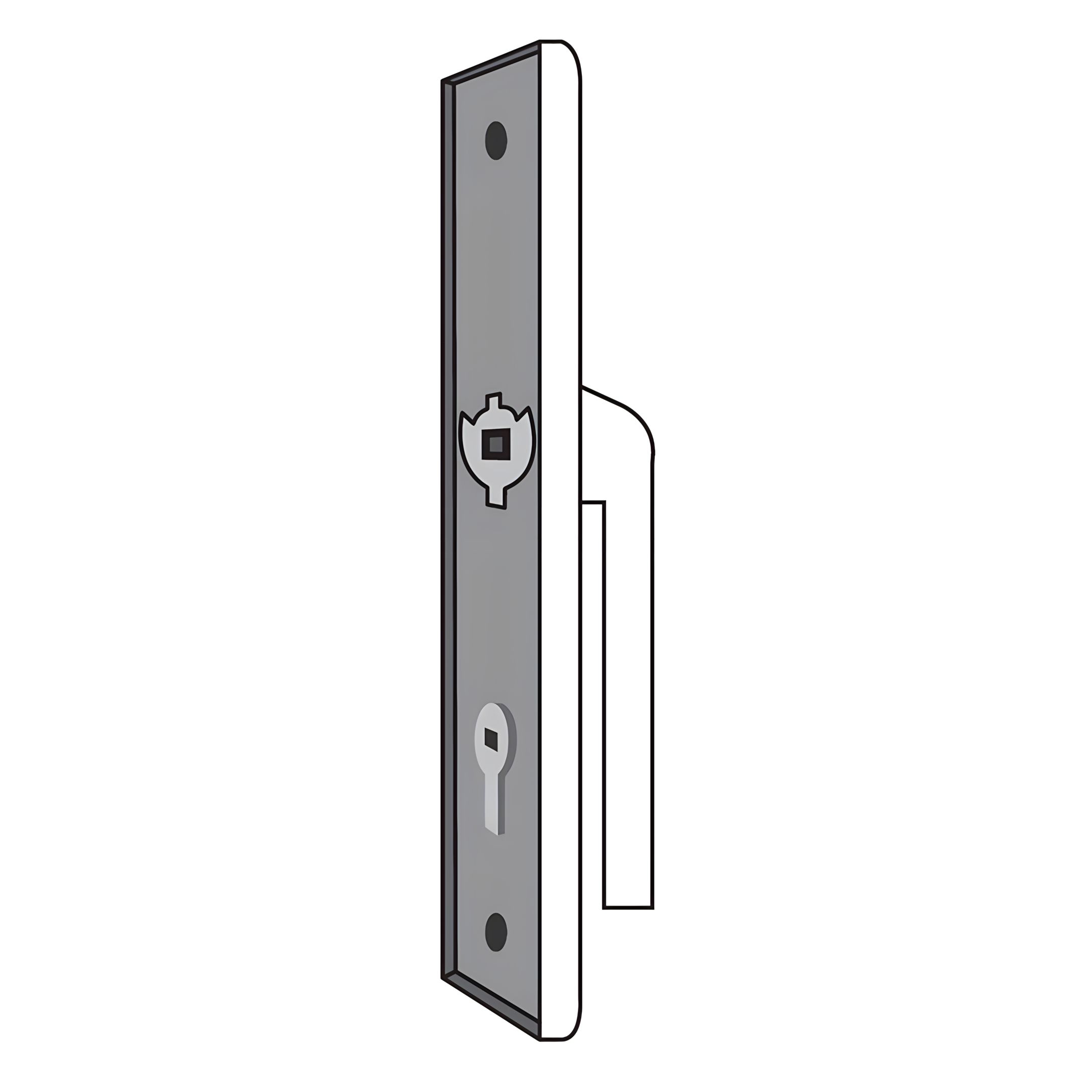
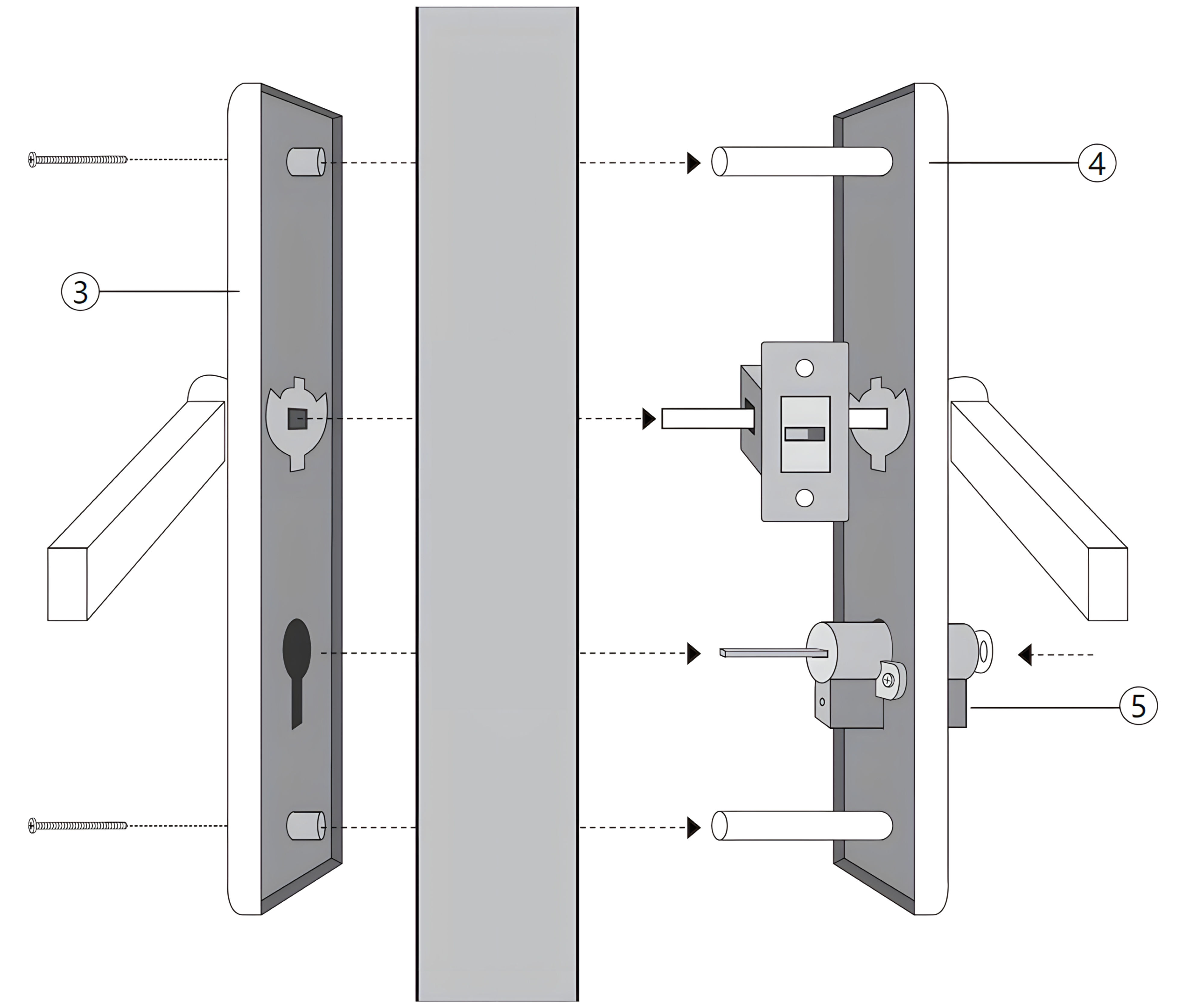
1. Position the Lock Handle Front Panel (Lock Part 3) on one side of the gate, aligning it with the designated holes. 2. Insert the Connecting Rod (Lock Part A) through the holes in the gate and into the Lock Handle Back Panel (Lock Part 4) on the opposite side. 3. Align the Latch Connecting Bar (Lock Part 2) with the slot in the back handle. 4. Secure the Key Mechanism (Lock Part 5) into the designated slot on the back handle using the Key Mechanism Screws (Lock Part 5-1). 5. Ensure all components are securely connected and aligned for proper lock functionality.
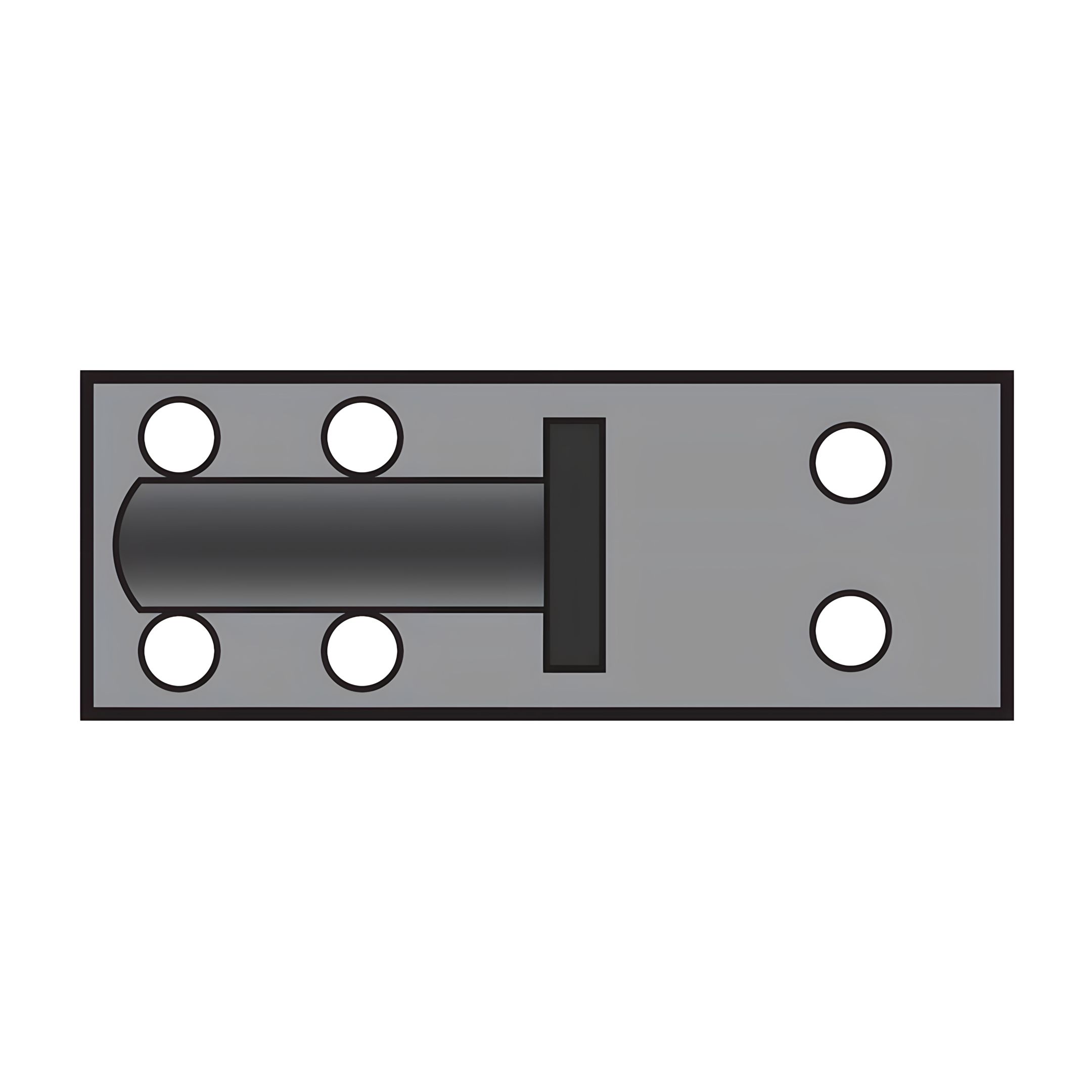
10. Latch Fitting Installation on Gate
To complete the installation of the latch fitting on the gate, follow these steps:
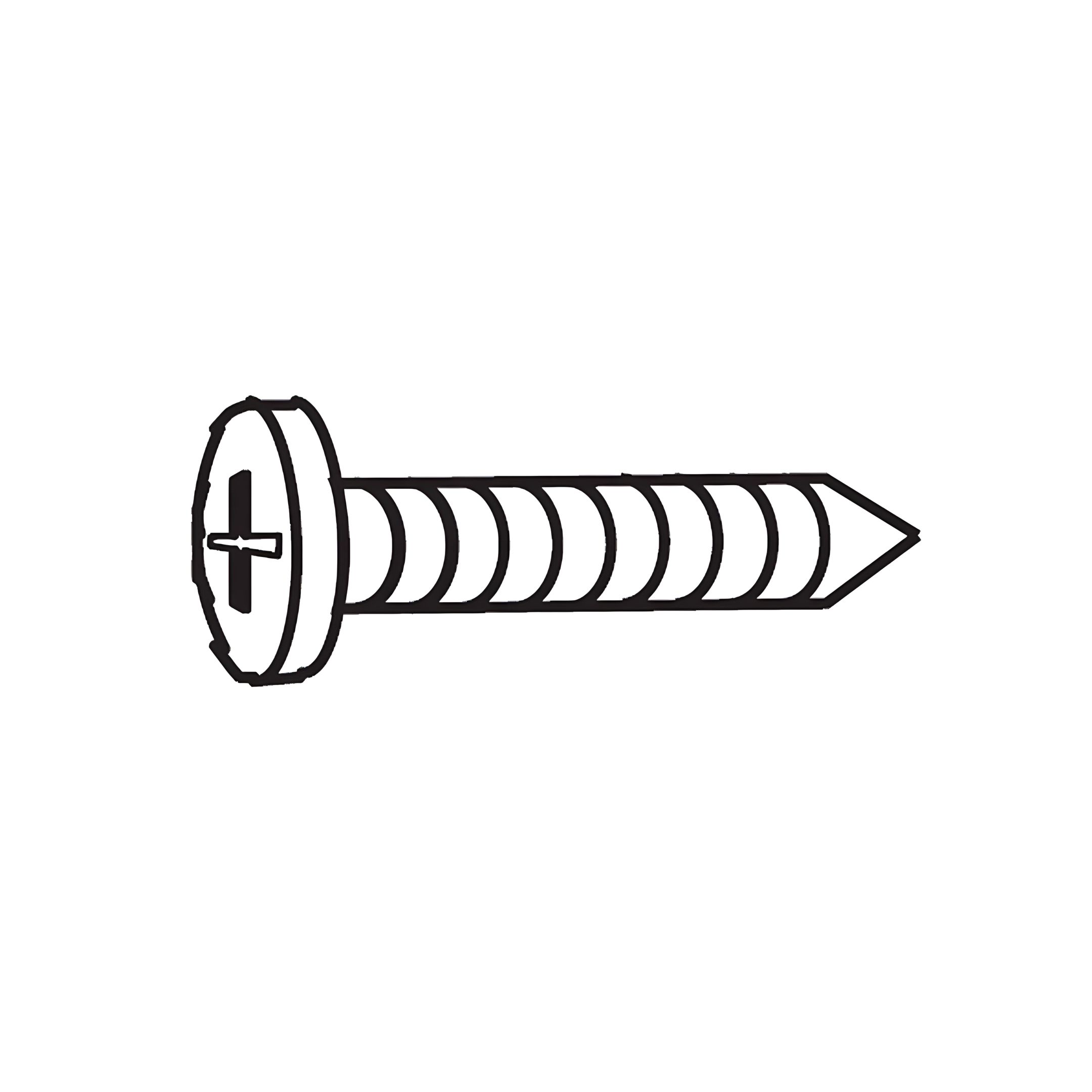
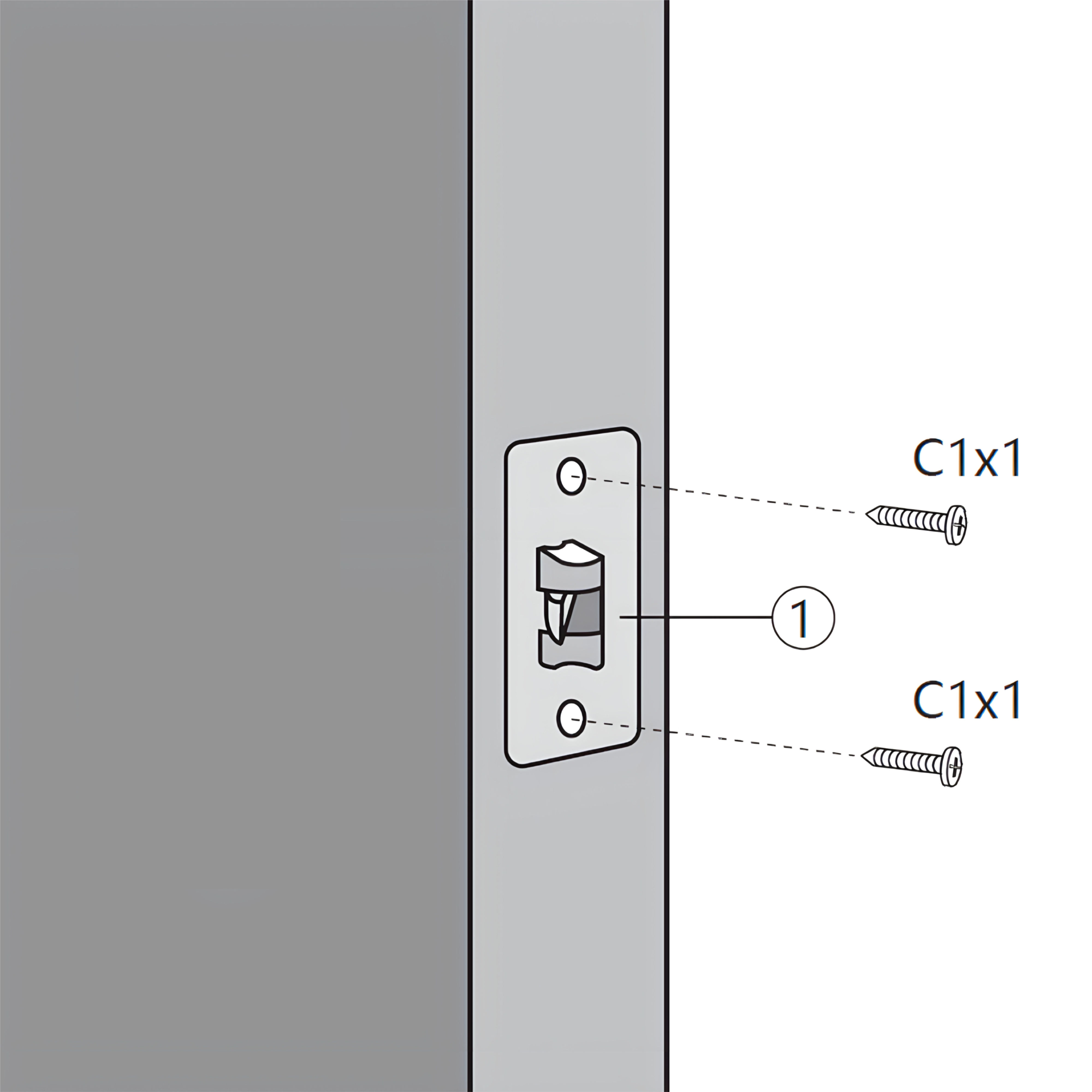
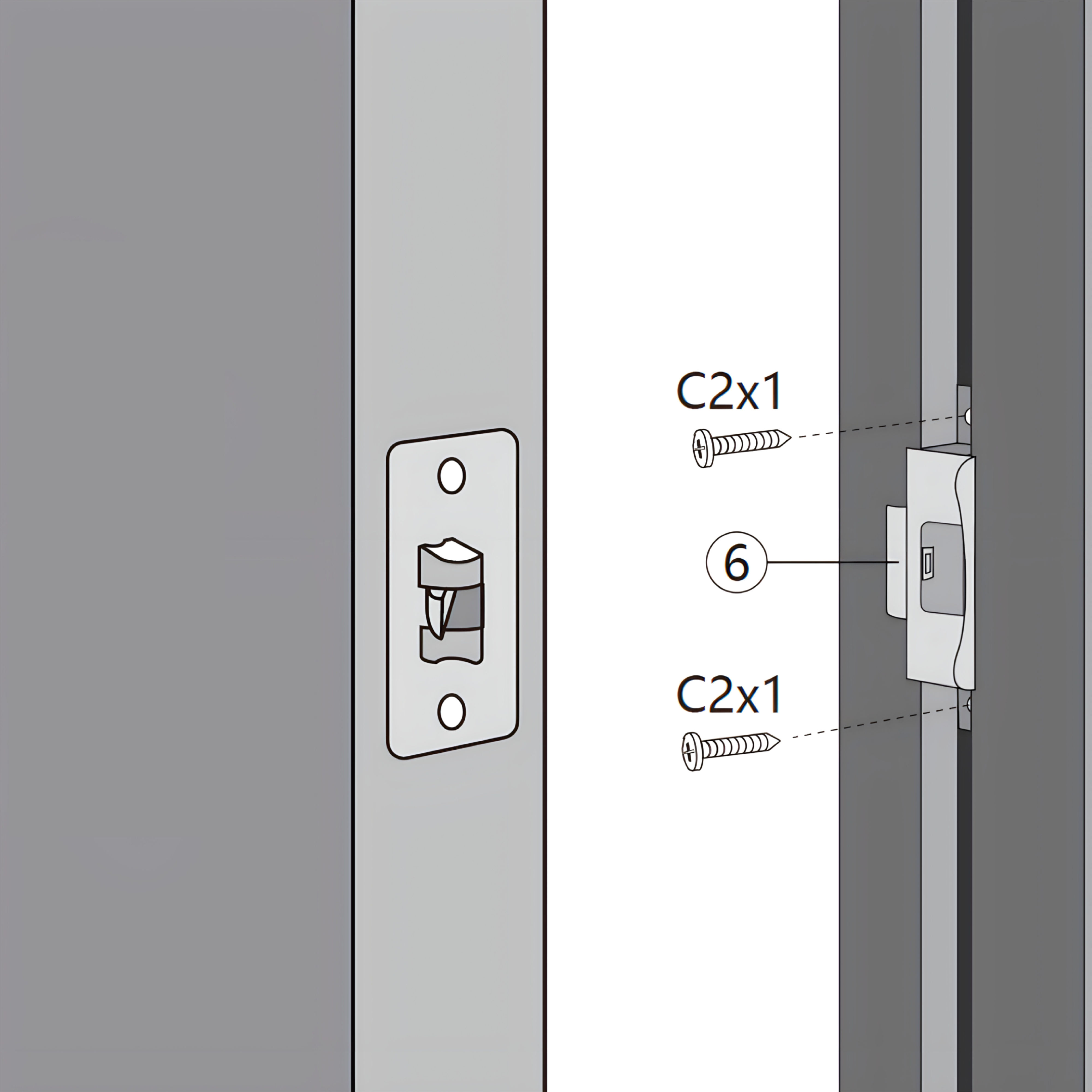
1. Position the Latch (Lock Part 1) on the gate frame, aligning it with the pre-drilled holes. 2. Position the Latch Fitting (Lock Part 6) on the Fence Post. Make sure to pre-drill holes to align latch fitting to correct height.. 3. Secure the latch fitting using two Latch Securing Screws (Lock Part C), ensuring it is firmly attached.
Ensure all components are securely connected and aligned for proper lock functionality.
11. Maintenance
Light Cleaning: Wipe down the gate surfaces occasionally with a damp cloth or rinse with water to keep them looking their best.
Hinge and Latch Checks: Periodically check hinges and latches to ensure they are securely fastened and operate smoothly.
Lighting Maintenance: Clean the solar panels on the LED lights regularly to maintain charging efficiency, especially during autumn when leaves can accumulate.
Avoid Impact Damage: Take care not to slam or force the gate closed, especially in high winds, to preserve structural integrity.
Monitor Gate Alignment: Ensure the gate remains properly aligned and adjust hardware if needed to maintain smooth operation.
12. Troubleshooting
WHAT DO I DO IF THERE ARE MISSING PARTS FROM MY ORDER?
If there appears to be any part missing from your order, contact our friendly and helpful Customer Support Team within 7 days of receipt.
FOR ALL OTHER ISSUES, PLEASE CONTACT OUR CUSTOMER SUPPORT TEAM.