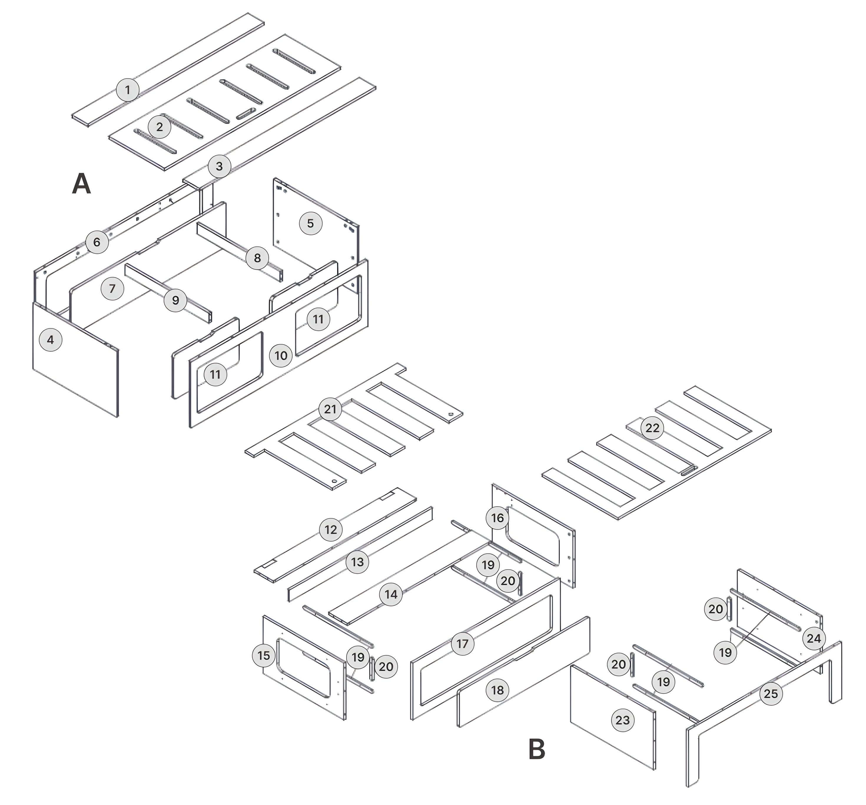
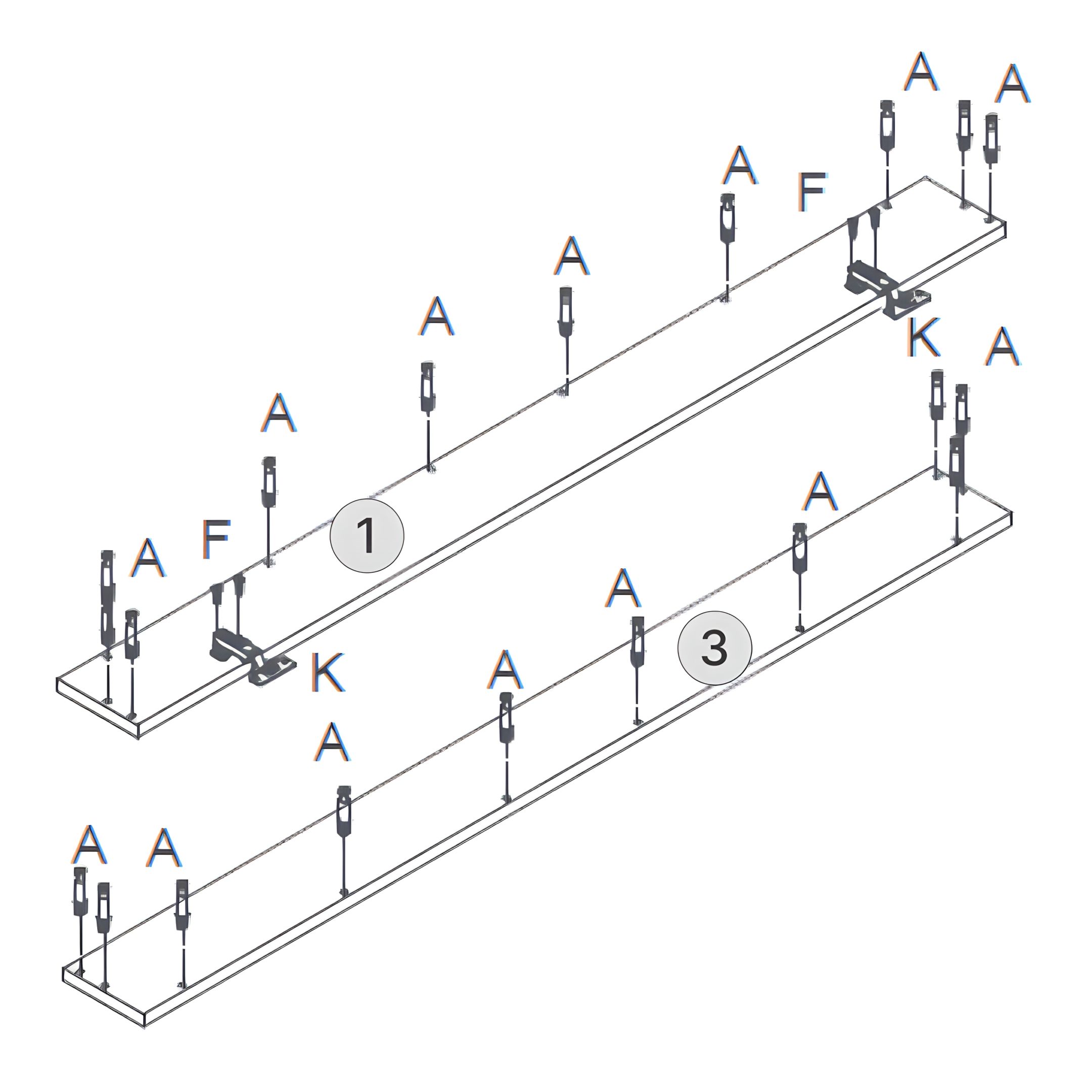
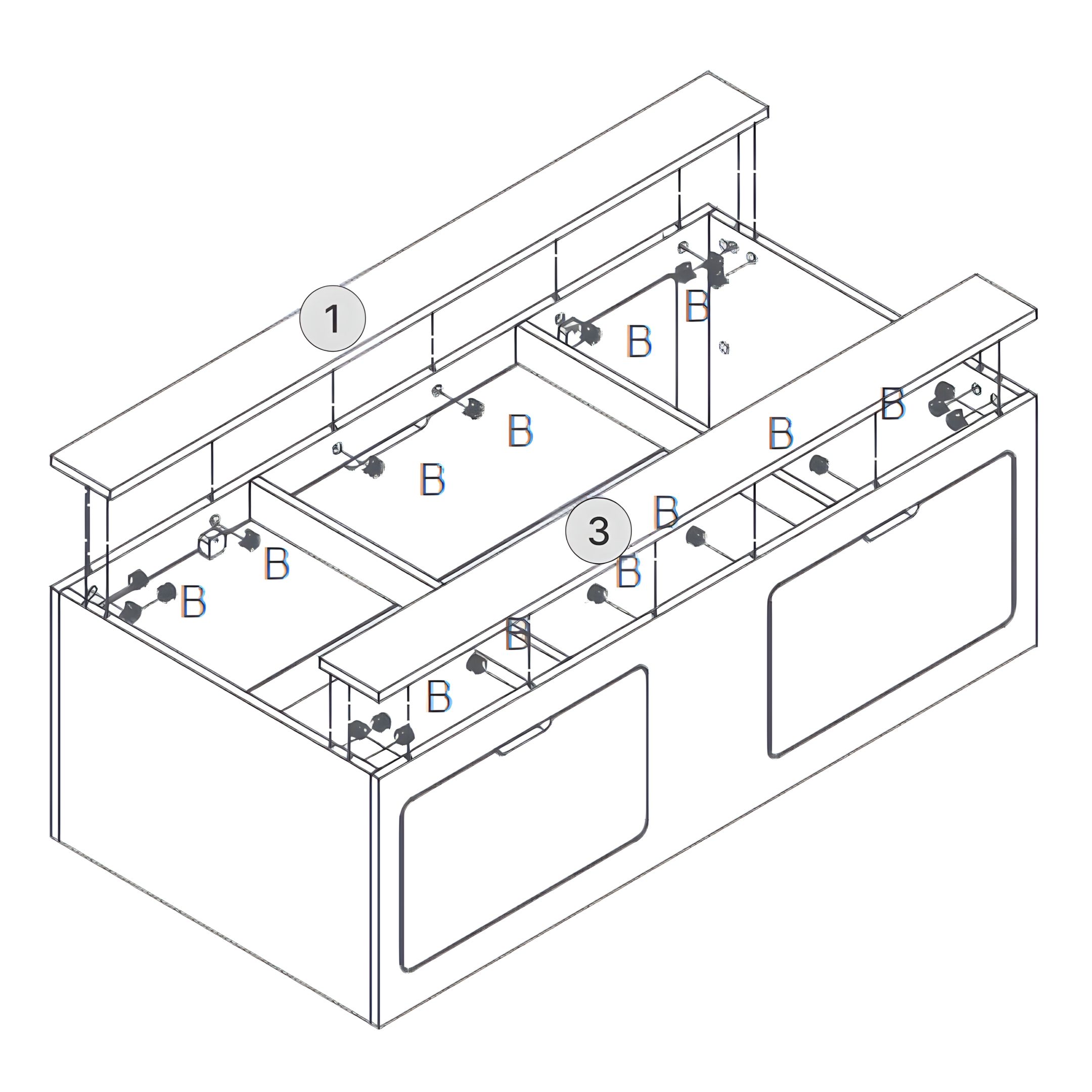
1Box A: Part 1 – Left Bench Front Rail
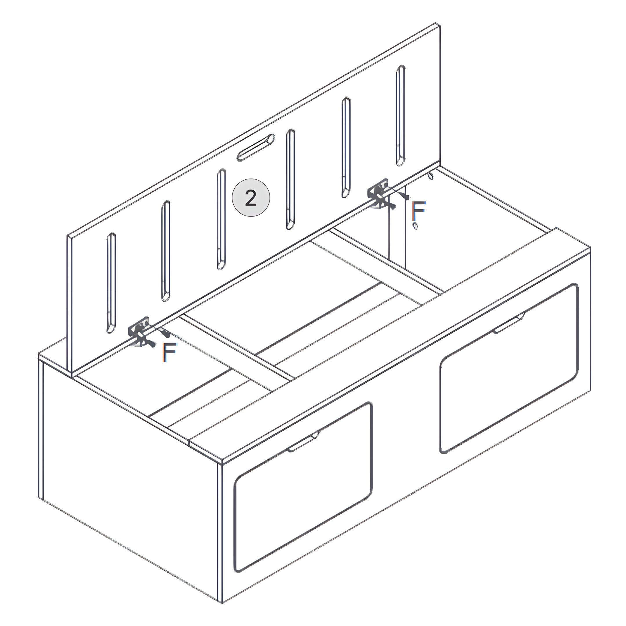
2Box A: Part 2 – Left Bench Lift-Up Lid
3Box A: Part 3 – Left Bench Back Rail
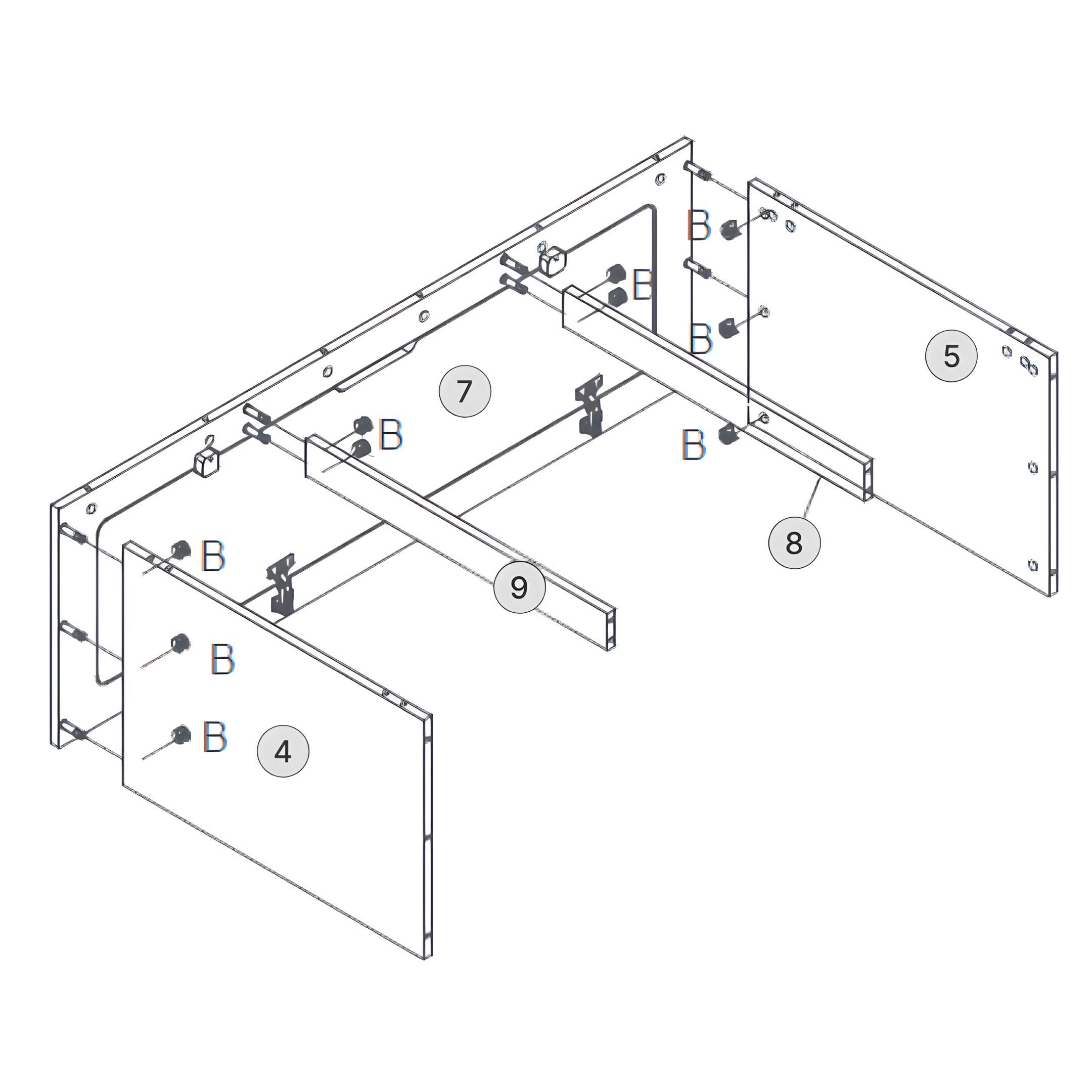
4Box A: Part 4 – Left Bench Side Panel (Front)
5Box A: Part 5 – Left Bench Side Panel (Back)
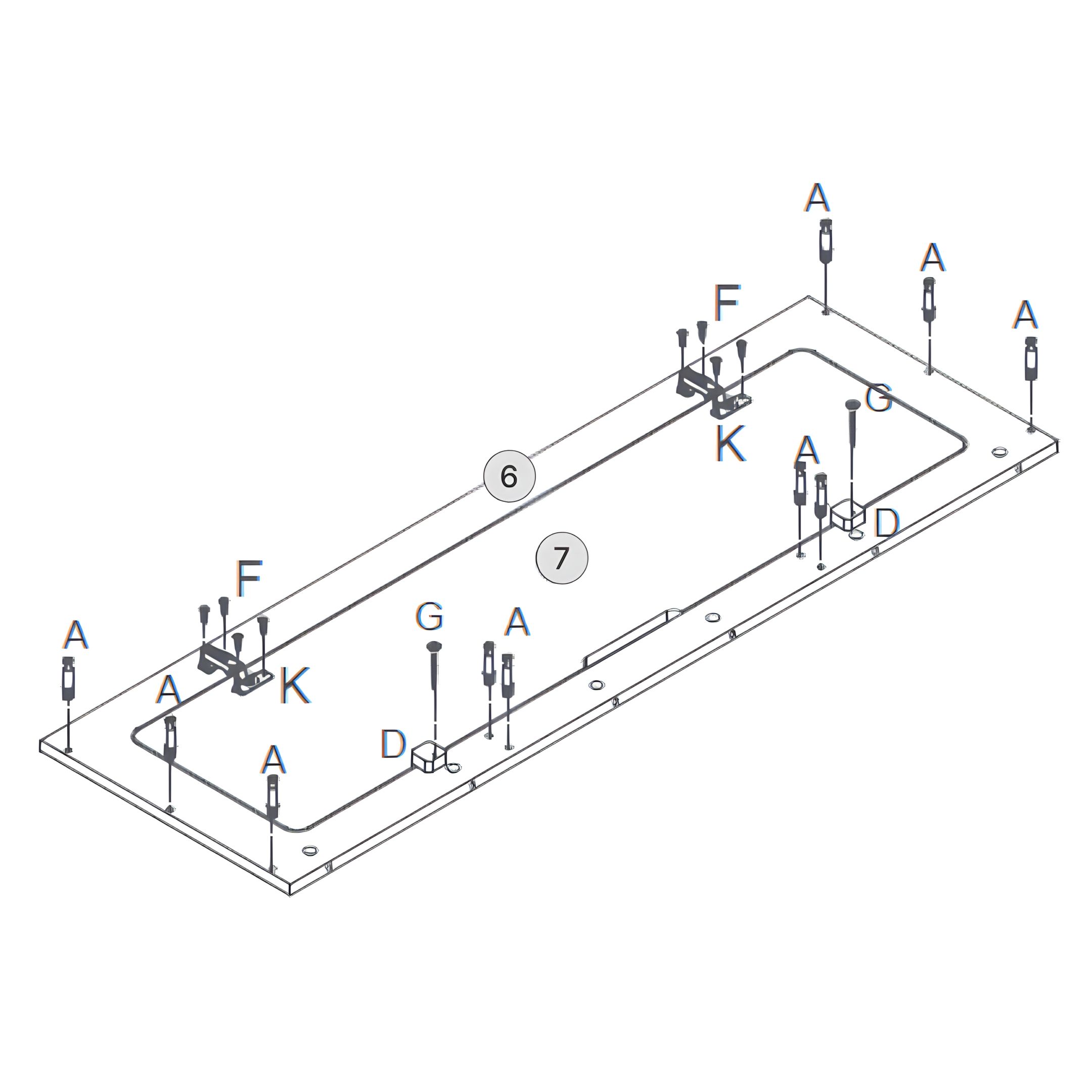
6Box A: Part 6 – Left Bench Top Frame (Surround)
7Box A: Part 7 – Door (Left Bench)
8Box A: Part 8 – Left Bench Inner Support Rails
9Box A: Part 9 – Left Bench Center Rail
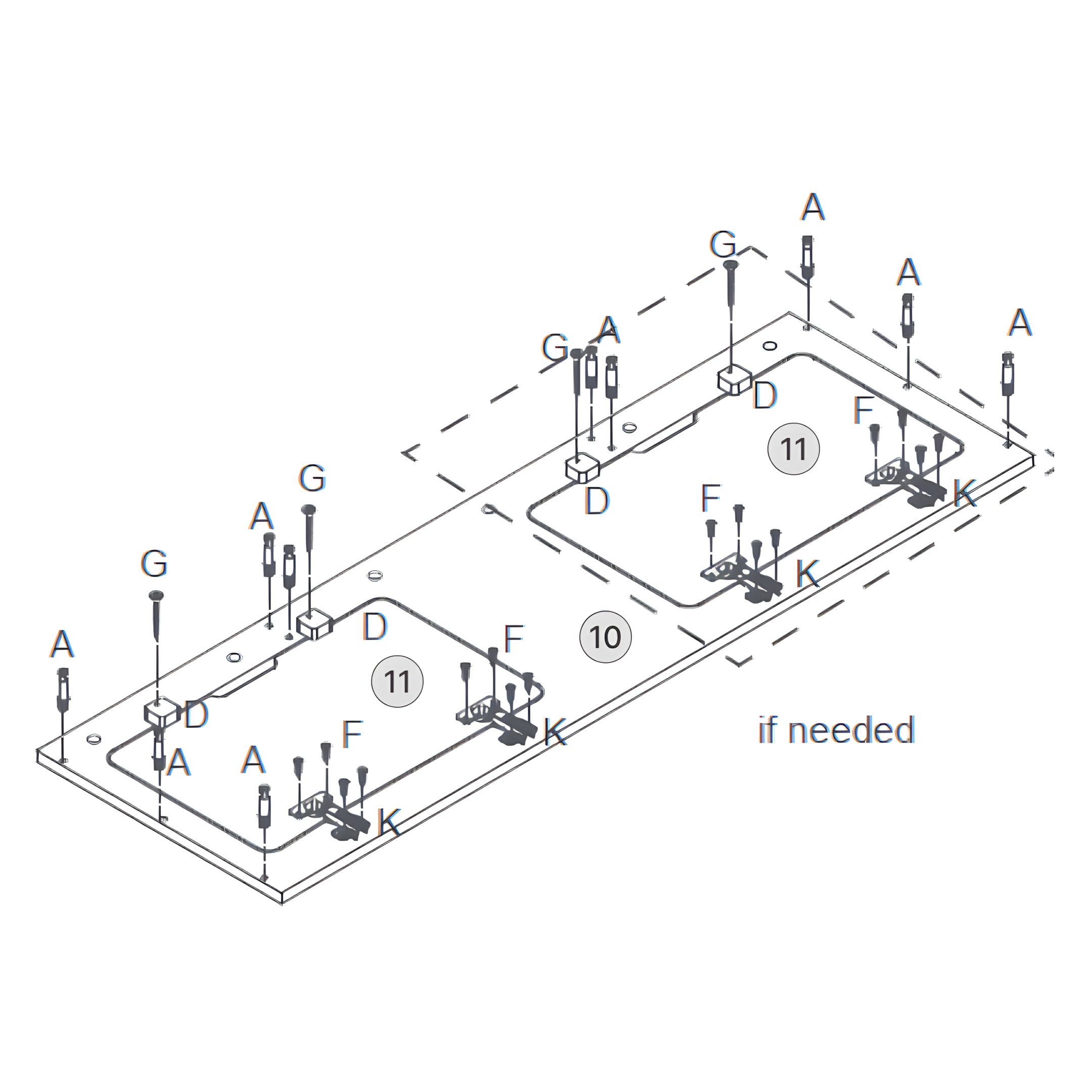
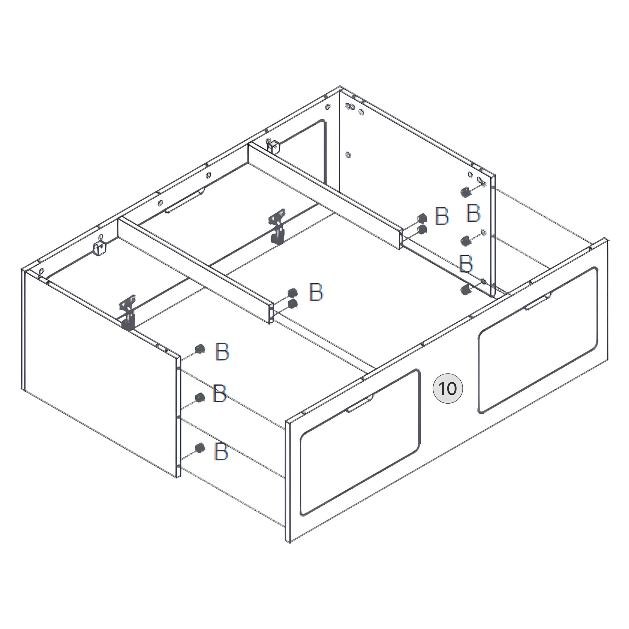
10Box A: Part 10 – Left Bench Front Panel with Cutouts
11Box A: Part 11 – Doors (Left Bench)
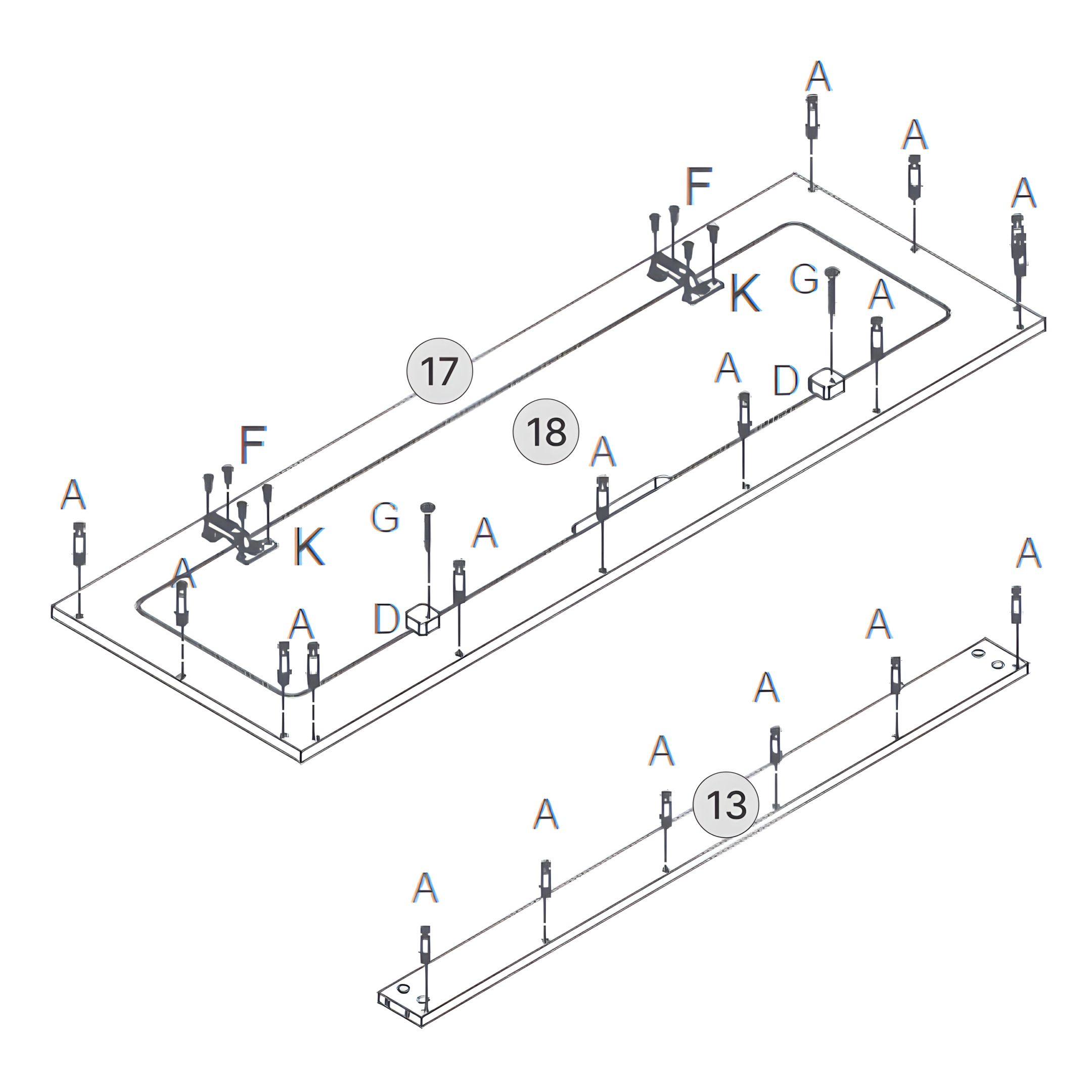
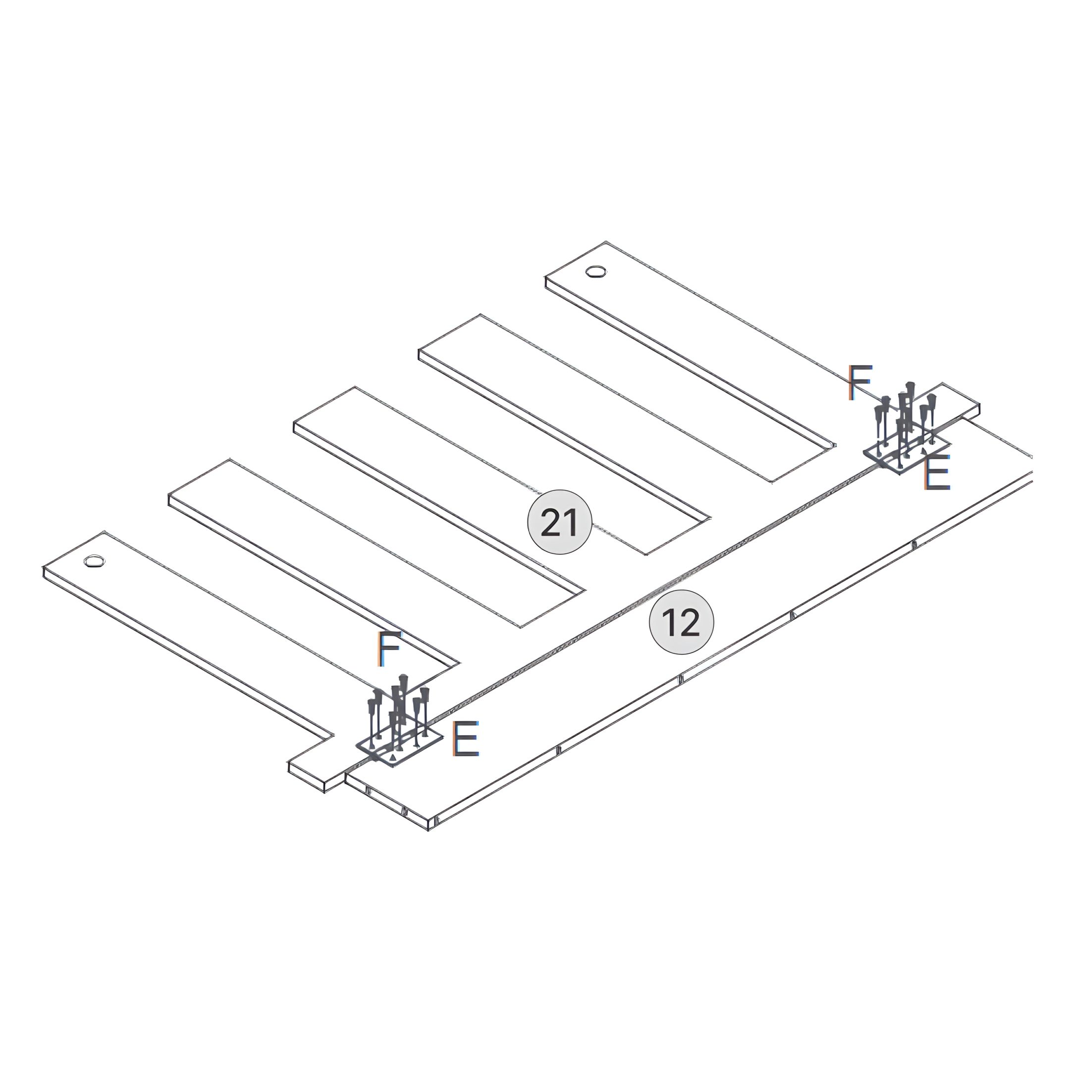
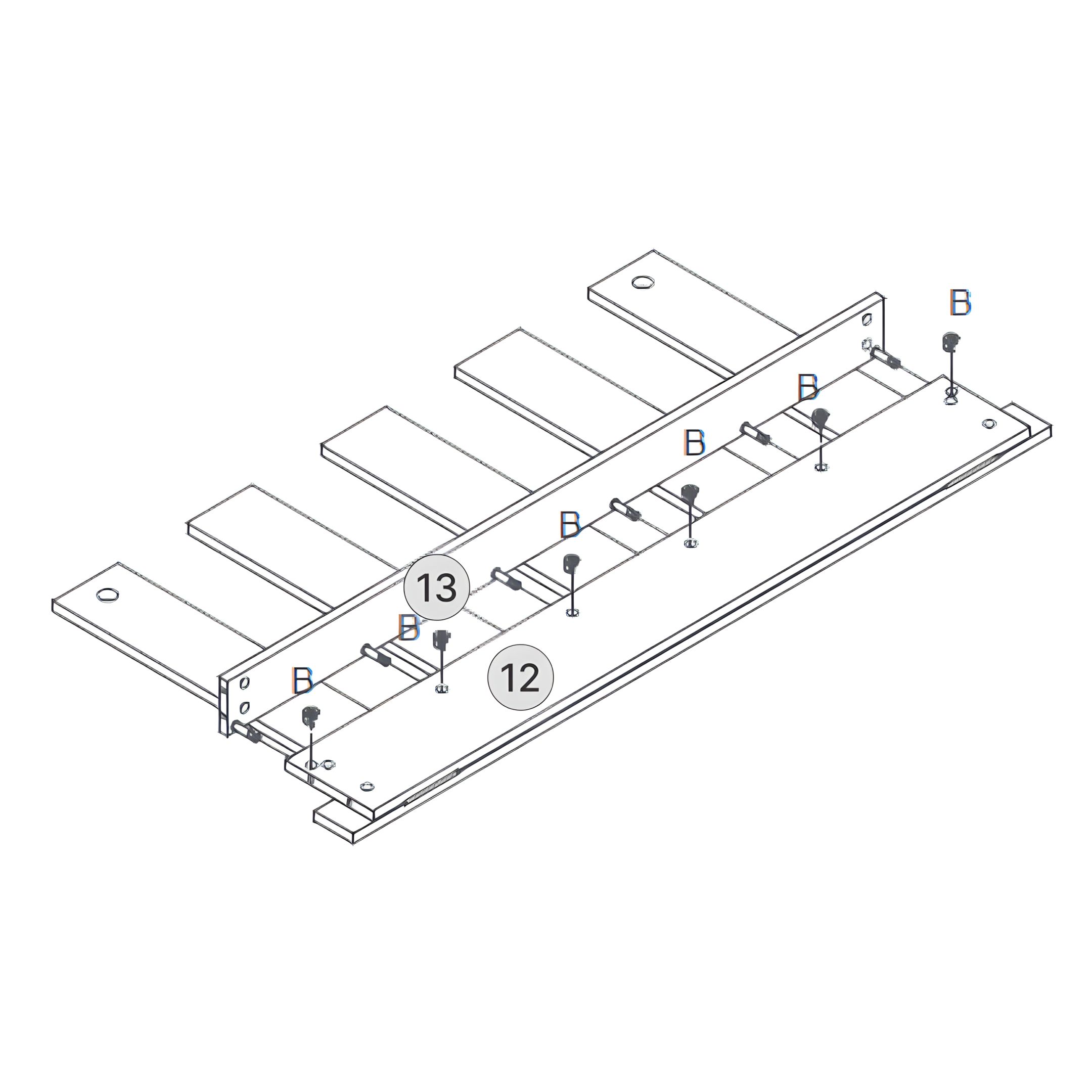
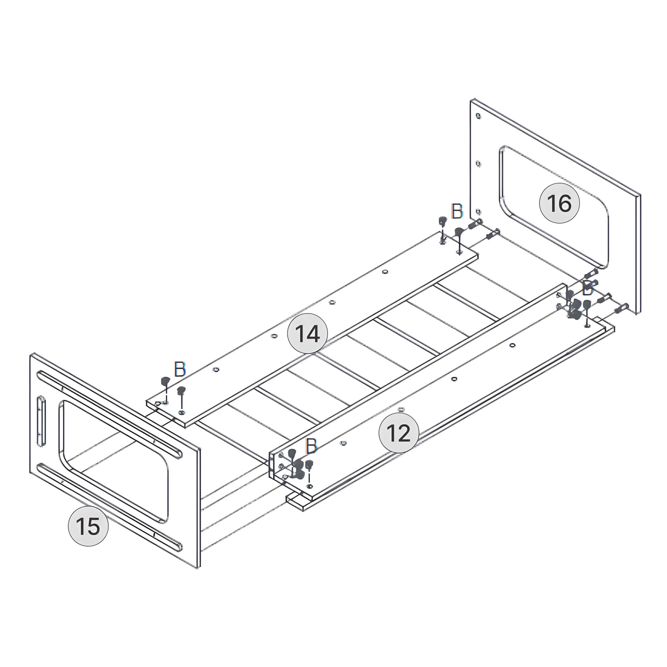
12Box B: Part 12 – Sliding Support Rail (Pull-Out Section)
13Box B: Part 13 – Pull-Out Slat Front Connector
14Box B: Part 14 – Right Bench Center Rail
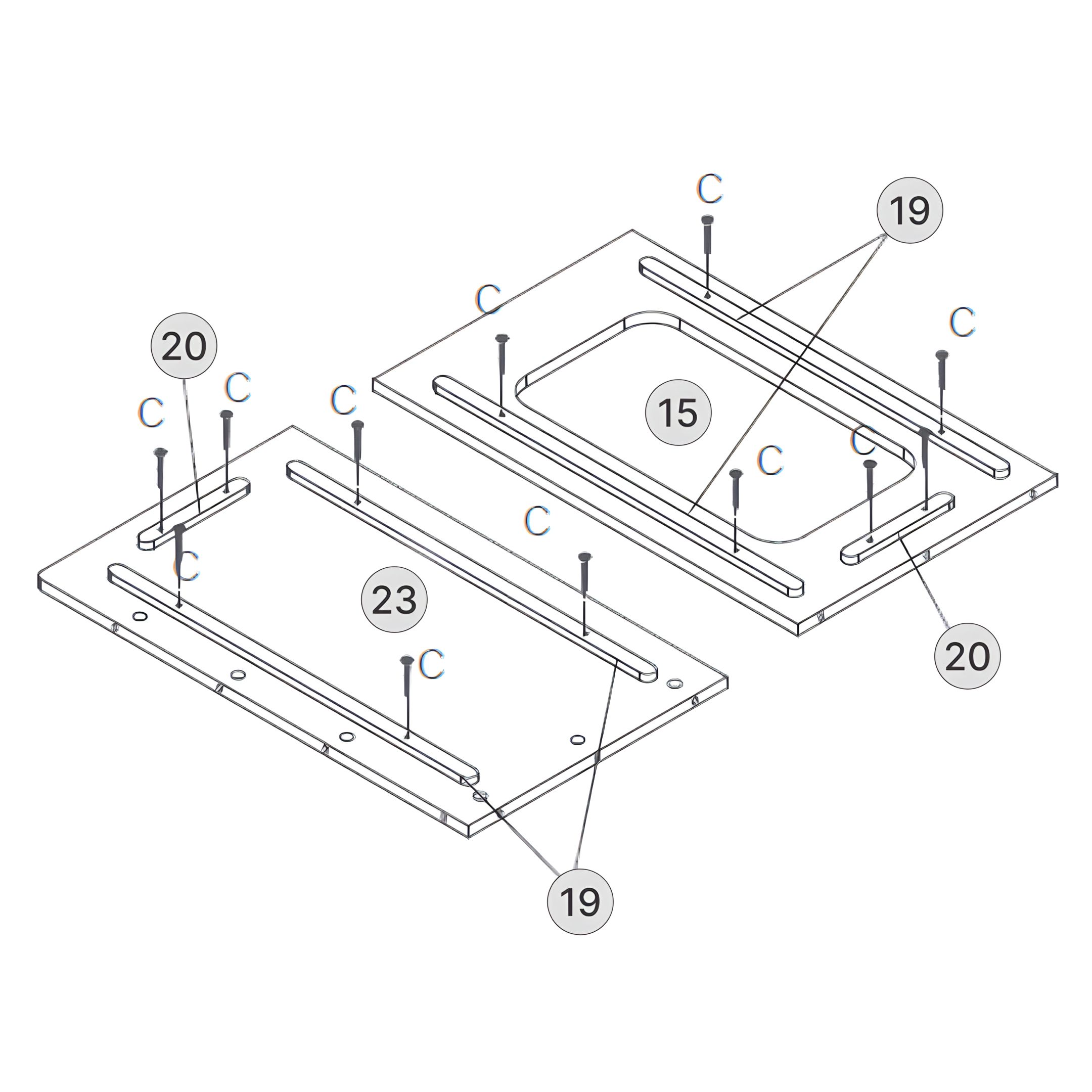
15Box B: Part 15 – Right Bench Side Panel (Front) with Cutout
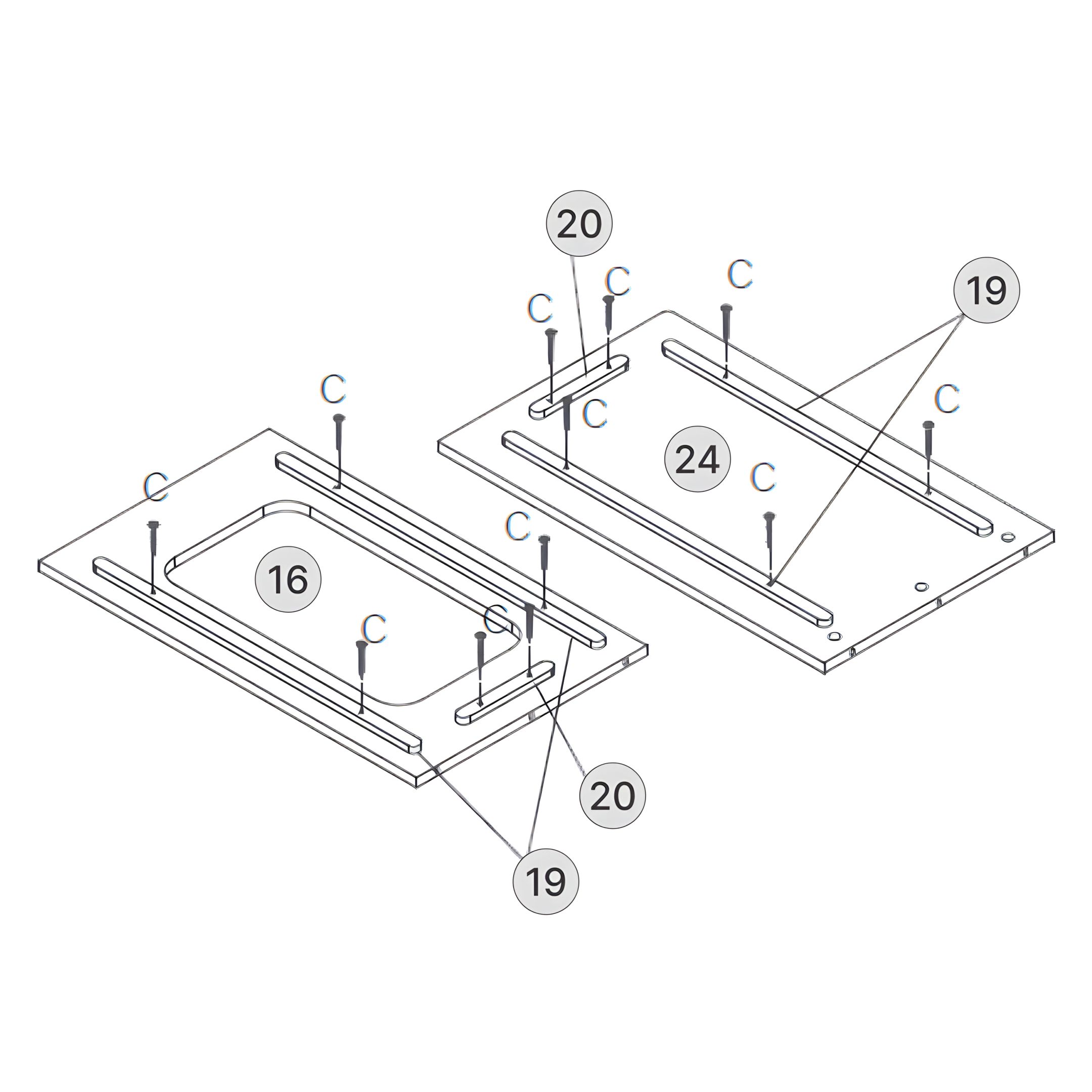
16Box B: Part 16 – Right Bench Side Panel (Back) with Cutout
17Box B: Part 17 – Right Bench Lid Frame
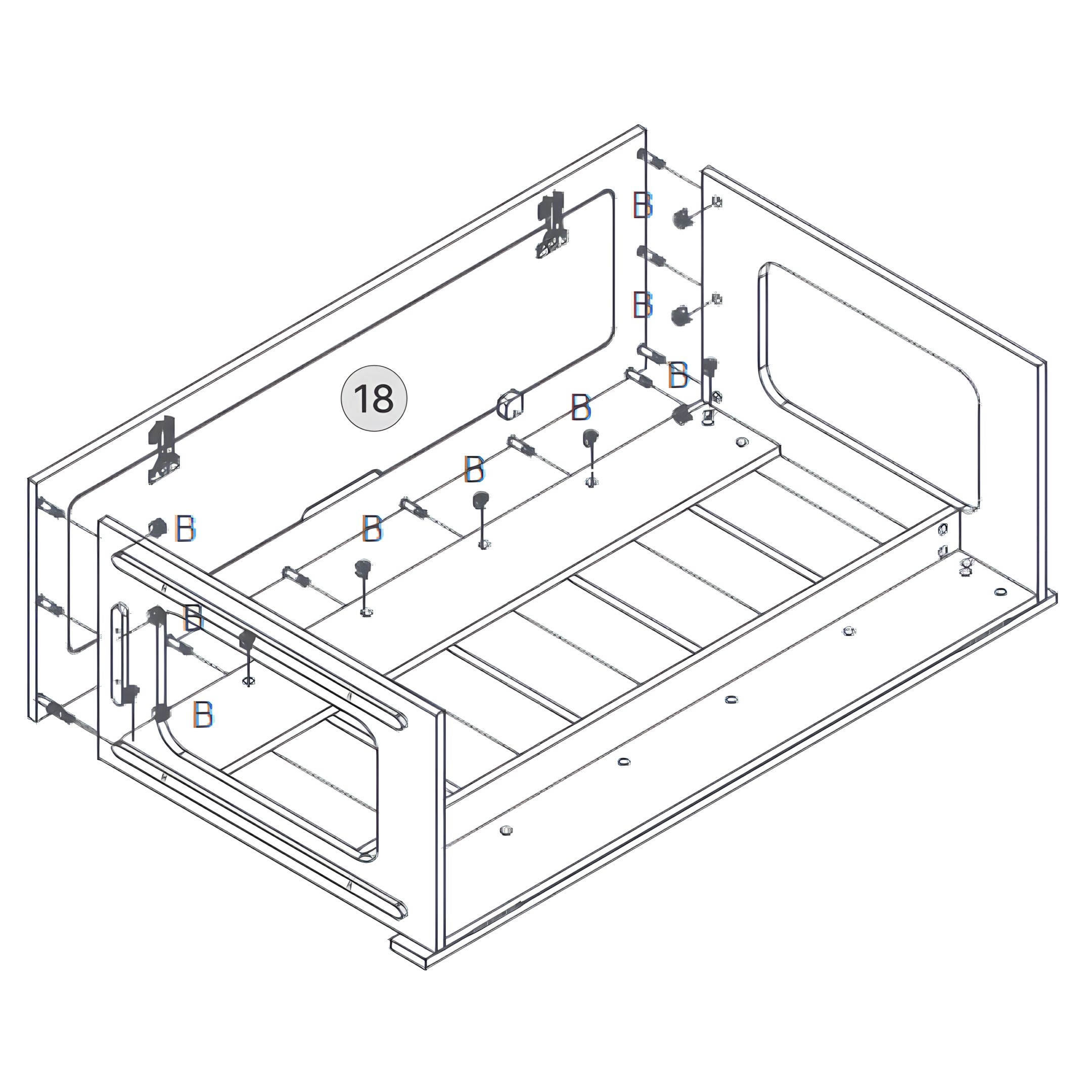
18Box B: Part 18 – Door
19Box B: Part 19 – Slat Guides
20Box B: Part 20 – Spacer Blocks for Slat Guides
21Box B: Part 21 – Slatted Pull-Out Bed Platform
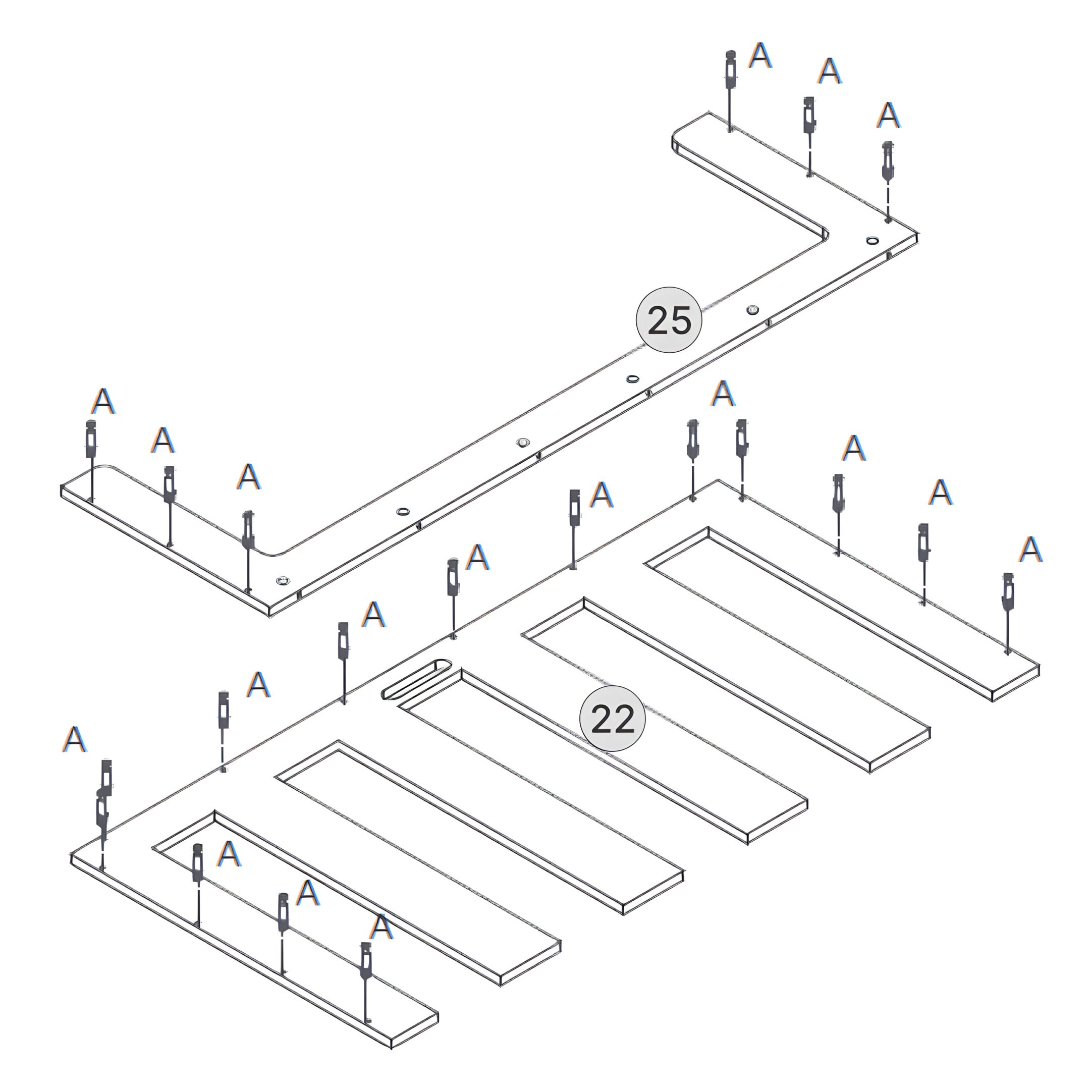
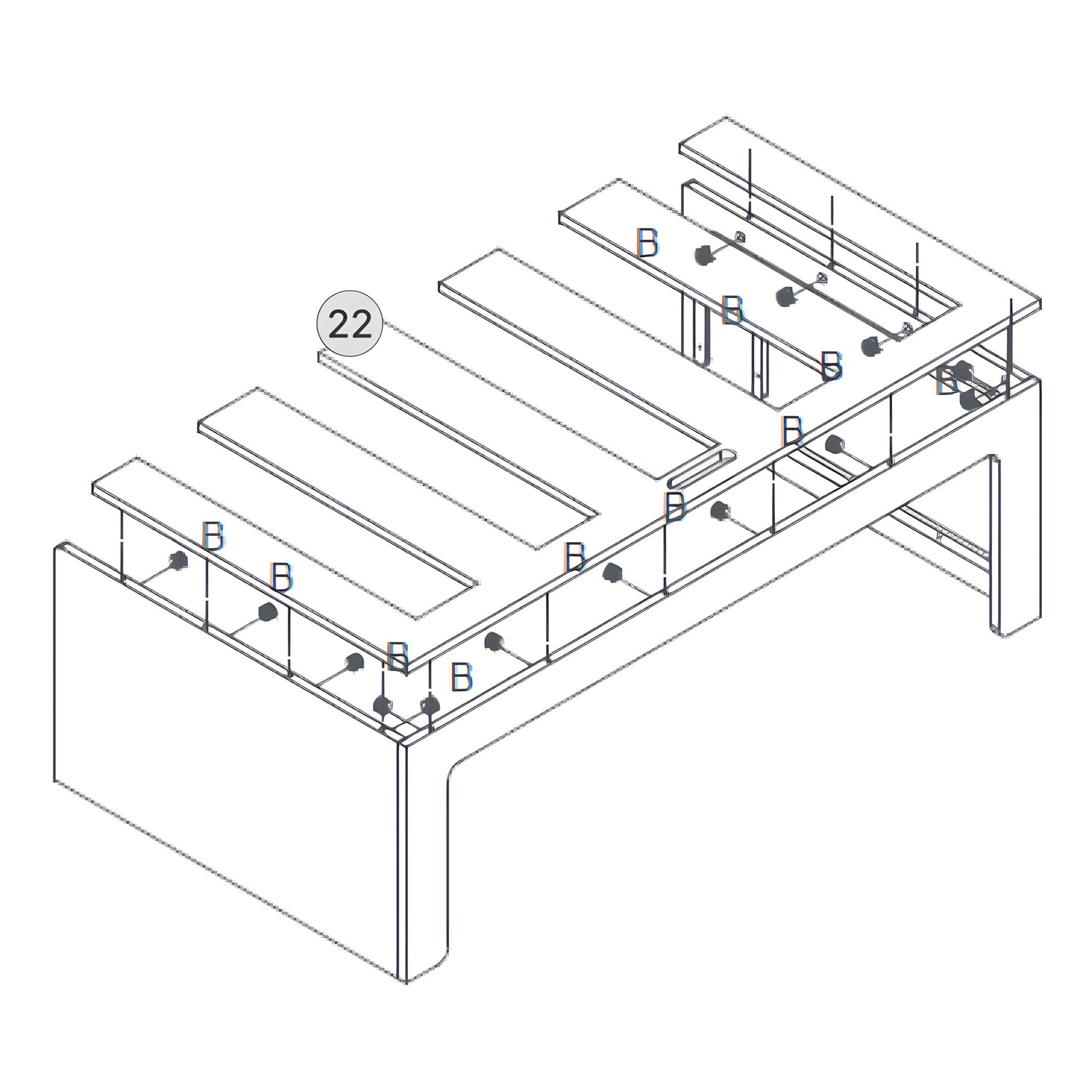
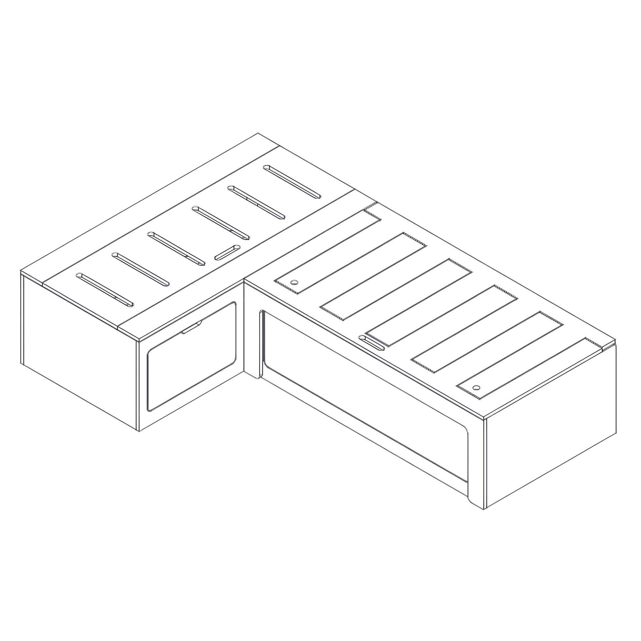
22Box B: Part 22 – L-Shaped Slatted Top Platform
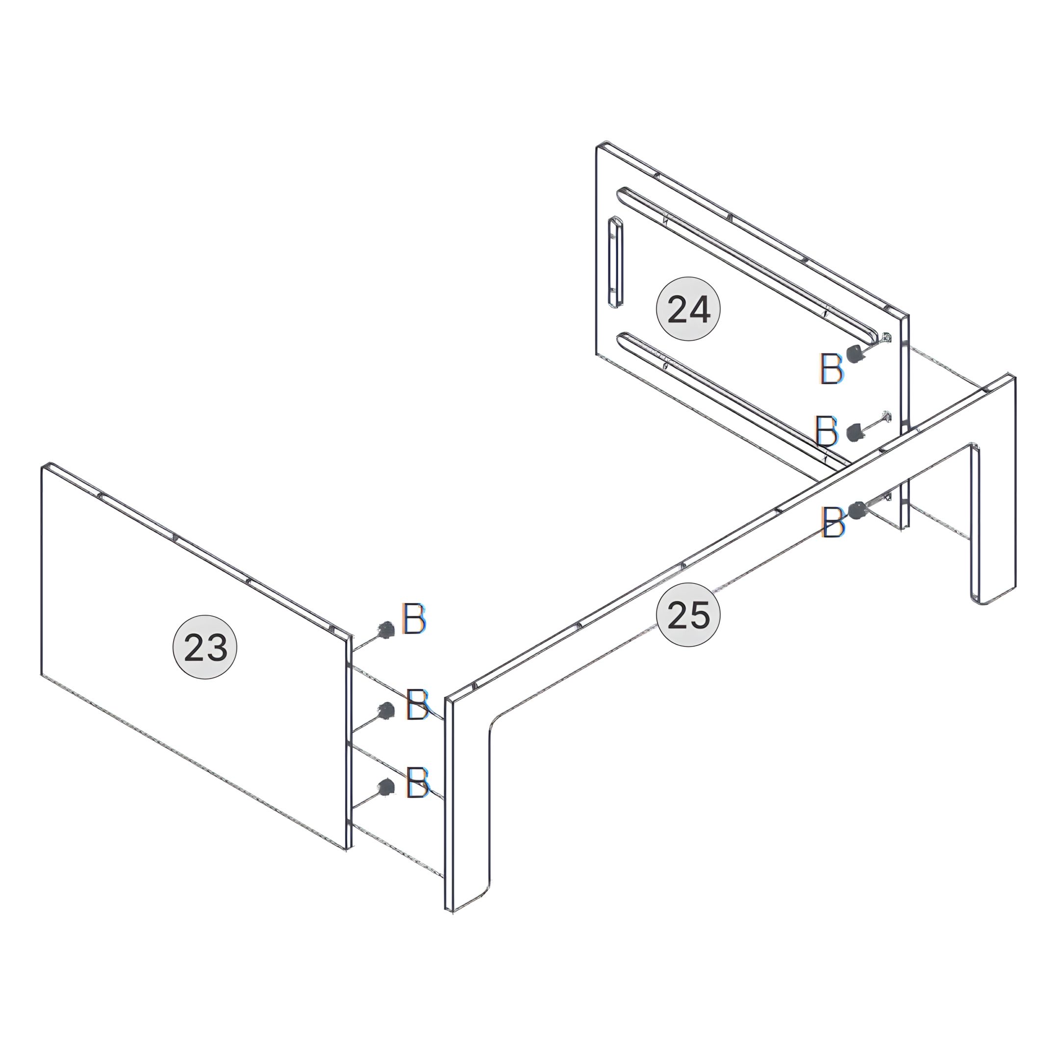
23Box B: Part 23 – Right Bench Rear Panel
24Box B: Part 24 – Right Bench Inner Back Panel with Slat Tracks
25Box B: Part 25 – L-Shaped Support Frame (Final Platform Base)
26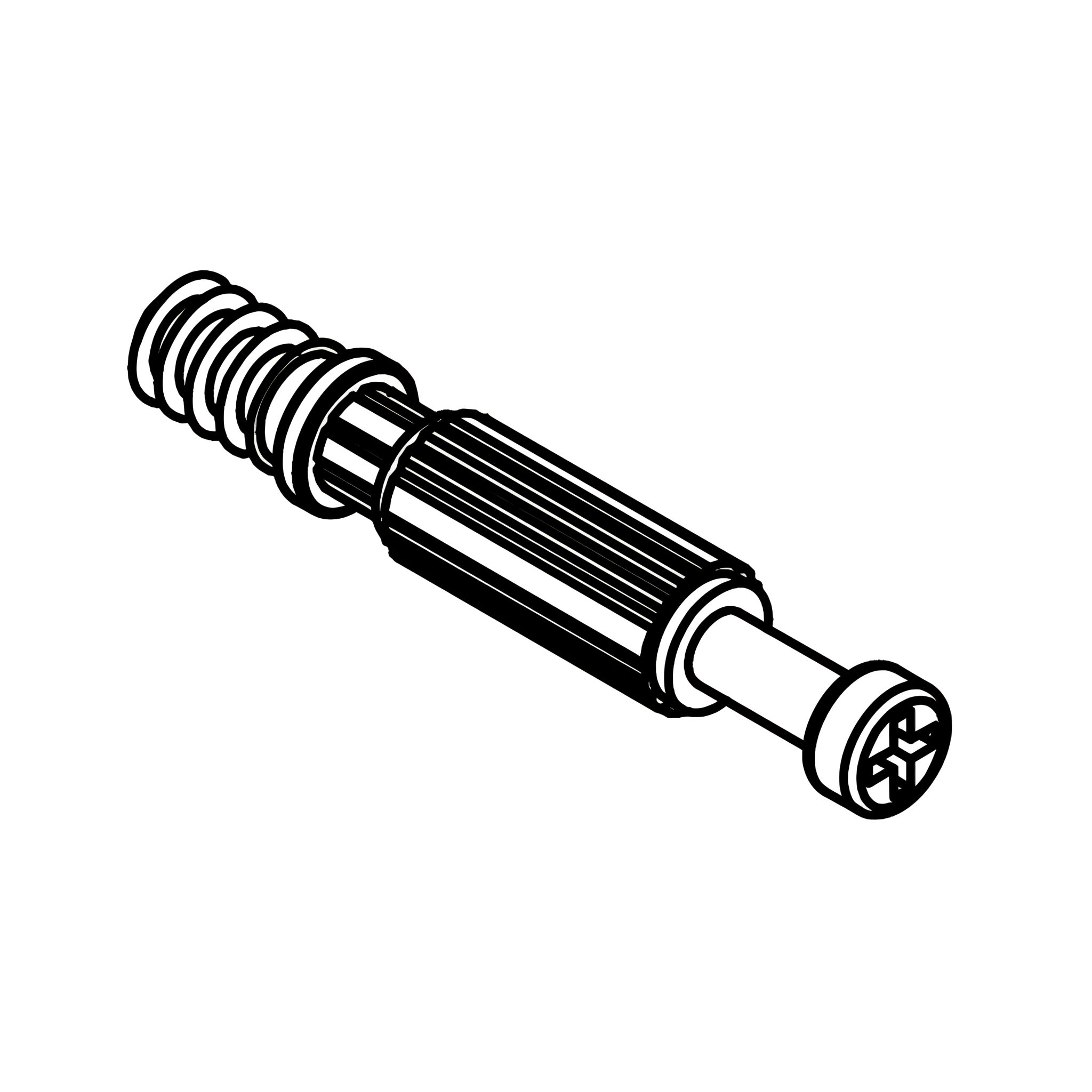 Box A: Part A - Connecting Bolt
 27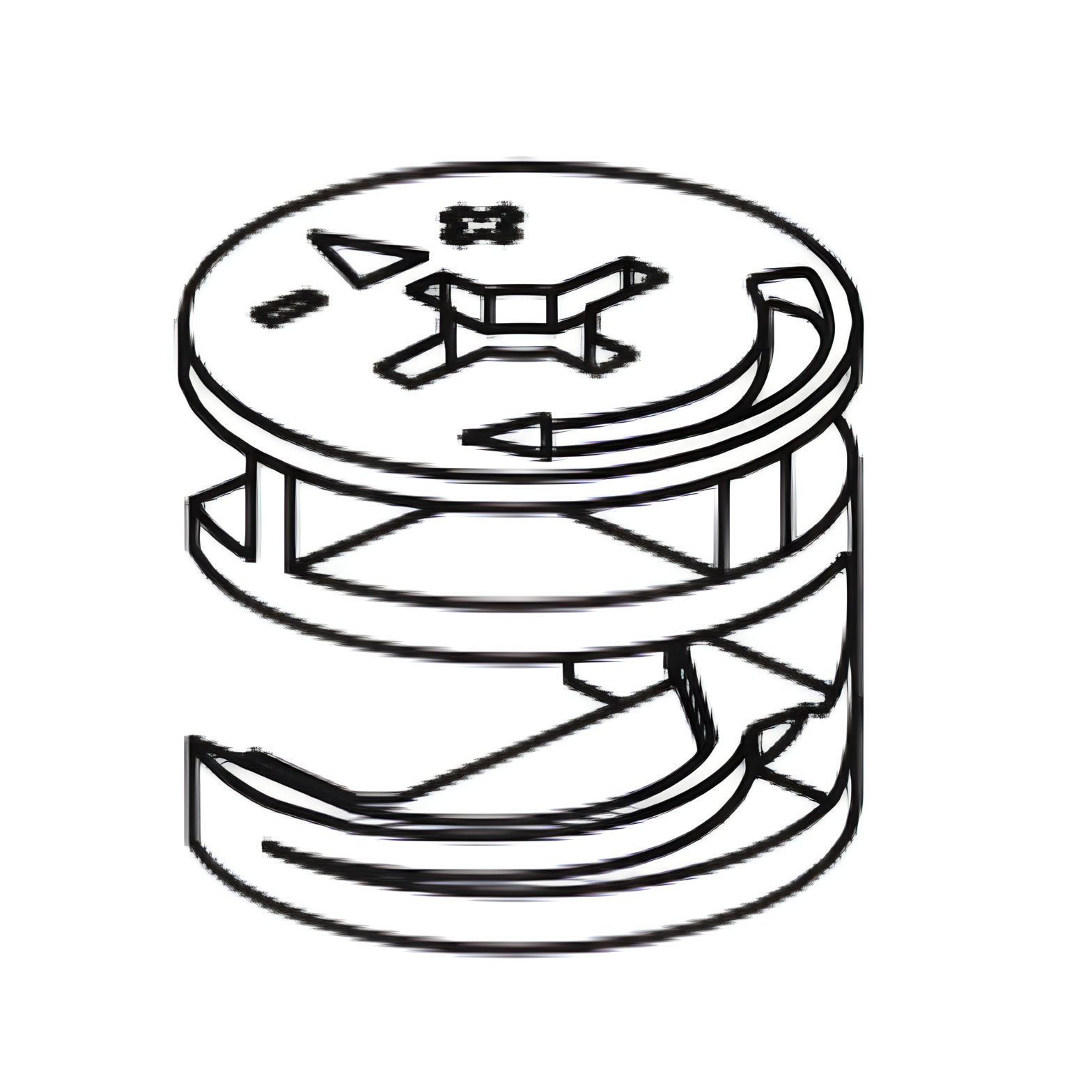 Box A: Part B - Cam lock
 28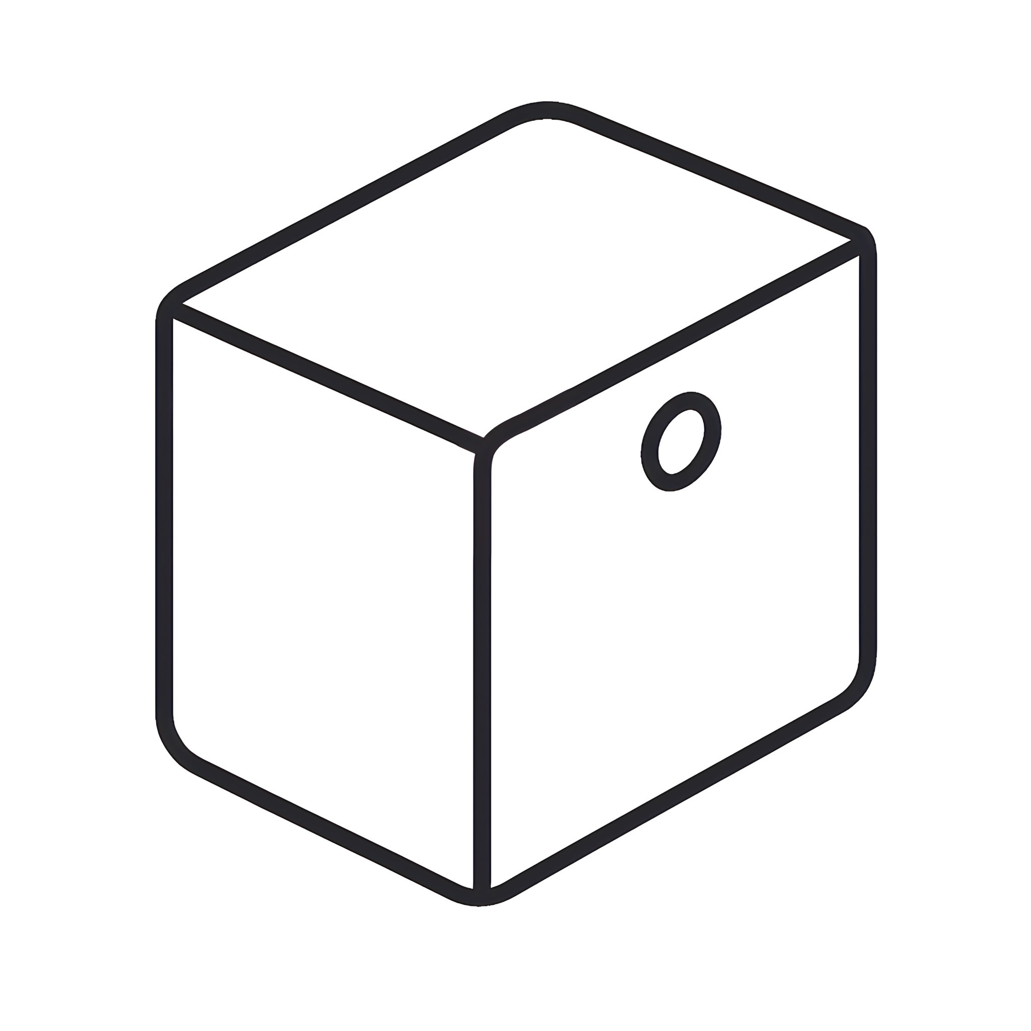 Box A: Part D - Support
 29 Box A: Part F - Screw 4 x 12mm
 30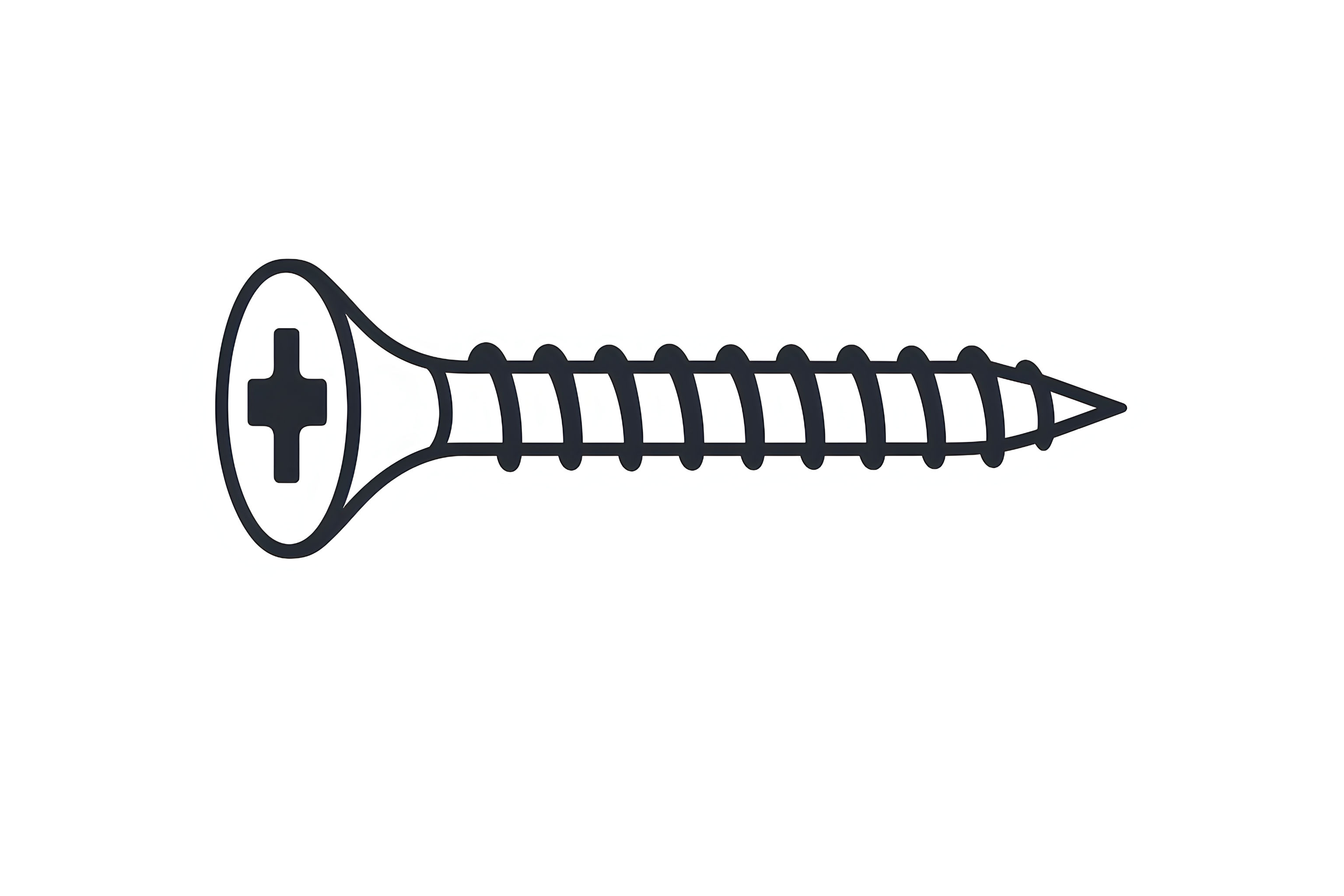 Box A: Part G - Screw 3.5 x 25mm
 31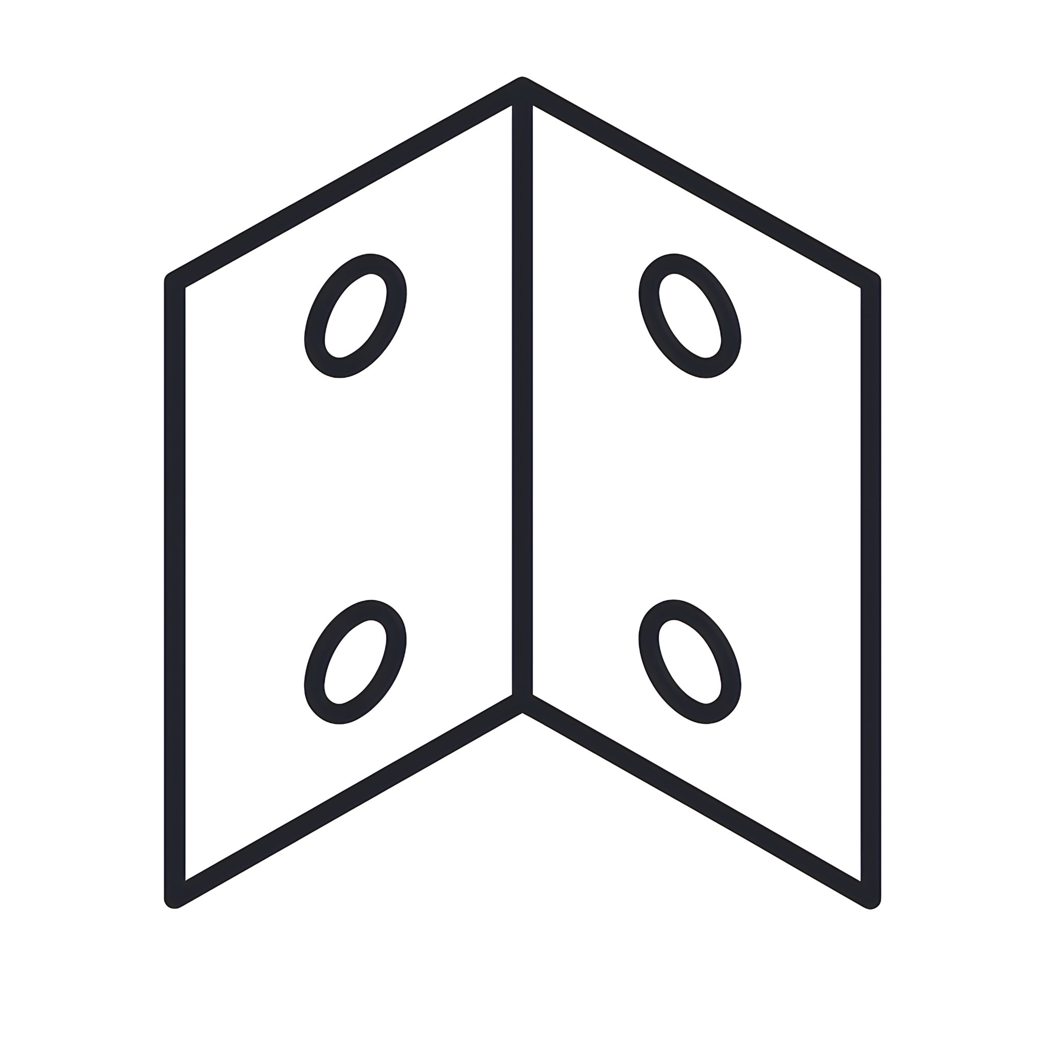 Box A: Part H - Corner Bracket
 32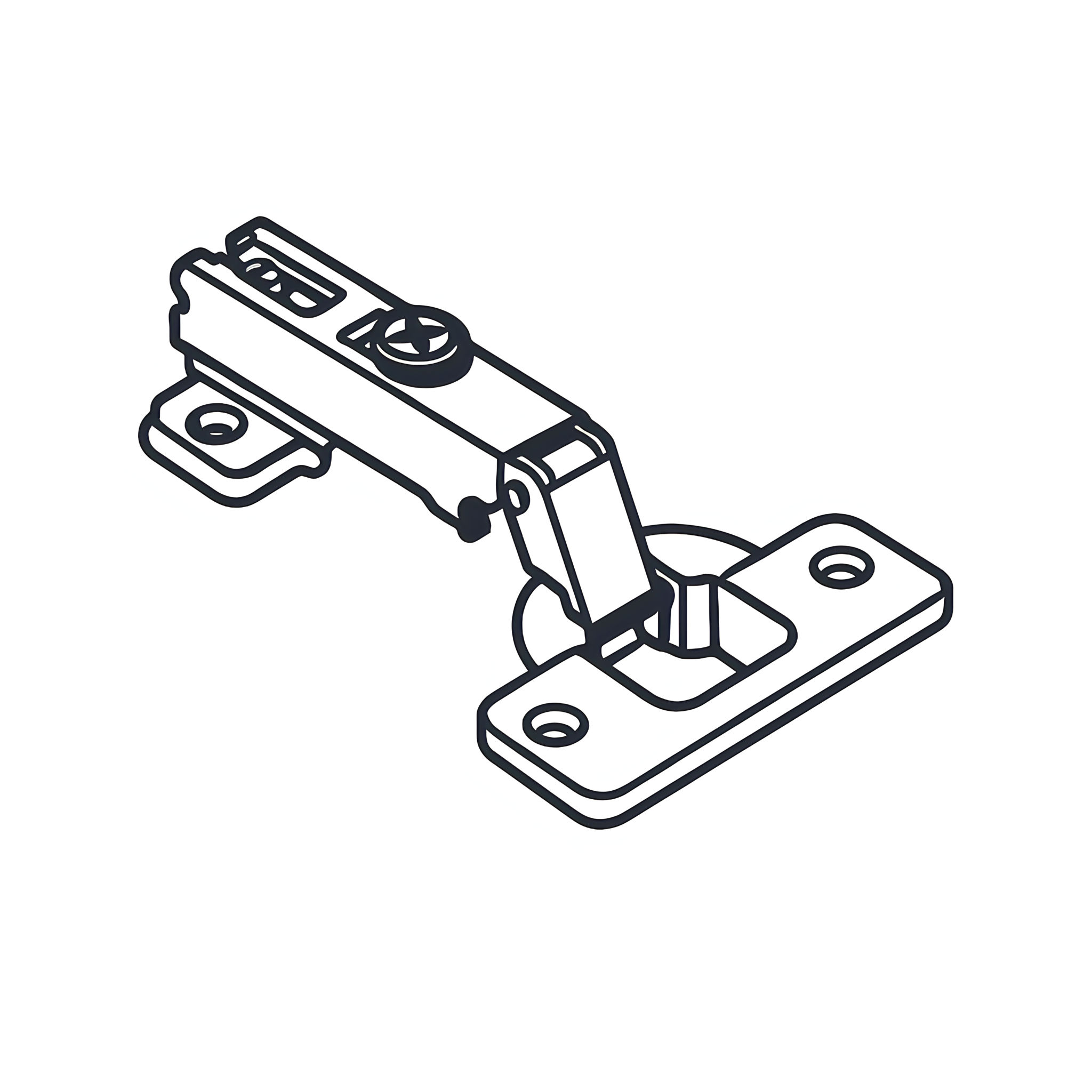 Box A: Part K - 90º Hinge
 33Box B: Part A - Connecting Bolt 34Box B: Part B - Cam lock 35Box B: Part C - Screw 3.5 x 20mm 36Box B: Part D - Support 37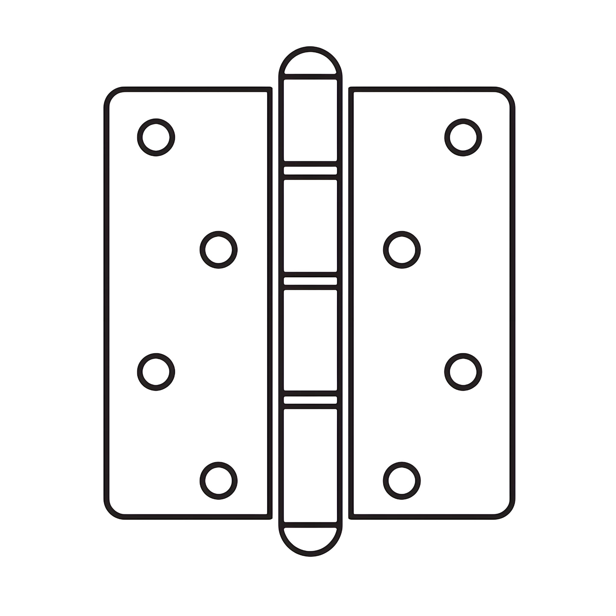 Box B: Part E - Hinge
 38Box B: Part F - 4x 12mm Screw 39Box B: Part G - 3.5x25mm Screw 40Box B: Part H - Corner Bracket 41Box B: Part K - 90º Hinge