Monster Manuals|
Cover

T-Mech Belt/Disc Sander 650W

This guide provides step-by-step instructions for assembling components and using the T-Mech Belt/Disc Sander 650W.
Product Information

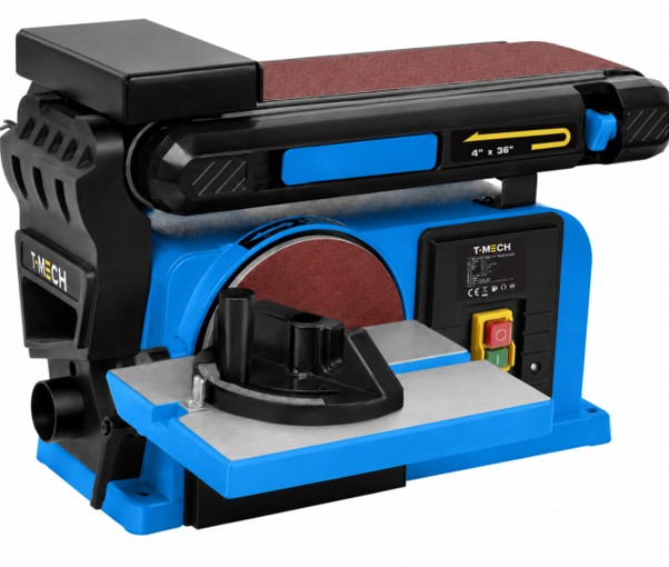
The T-Mech 650W Belt & Disc Sander combines a 100 × 914mm belt sander and 150mm sanding disc in one versatile machine for sanding, shaping and finishing wood, plastics and other suitable non-ferrous materials. Featuring a powerful and quiet induction motor, an adjustable 0–45° worktable and a belt that can be used horizontally or vertically, it provides flexibility for a wide range of workshop applications. Quick abrasive belt replacement and a dust extraction port help improve convenience and maintain a cleaner working environment.

SKU 218392
Voltage/Frequency 230/50Hz
Power 650W
Load Speed 3500min-1
Belt Dimensions 4x36''(100x914mm)
Disc Diameter 4''(Ø150mm)
Disc Speed 3250rpm
Belt Speed 1700fpm(8m/s)
Gross Weight 16kg
Material Cast Iron, Stainless Steel, ABS
Features Belt and disc two-in-one sanding machine
Belt can be working horizontally and vertically
Adjustable table can be tilted from 0°-45°
Quick and easy belt replacement
Reasonable dust removable system design
Powerful and silent induction motor
Soft Grinder tool

Safety Information

Saftey Advice

Ensure you have read and fully understood the instruction manual and safety advice before using this product.
• This product is intended for sanding, shaping and finishing suitable wood, plastics and other compatible non-ferrous materials only. Do not use it for cutting, grinding, polishing or any other unintended purpose.
• This product is intended for use by competent adults only. Keep children and unauthorised persons away from the work area.
• Assemble the machine fully before use and ensure all guards, tables and accessories are correctly fitted and securely fastened.
• Secure the machine to a stable, level workbench before operation to prevent movement or tipping.
• Inspect the machine, sanding belt, sanding disc, power cable and plug before each use. Do not use if any component is damaged, excessively worn or loose.
• Ensure the sanding belt and disc are correctly installed, properly tensioned and suitable for the material being sanded.
• Keep hands, fingers, loose clothing, jewellery and long hair away from all moving abrasive surfaces.
• Never reach across the moving belt or sanding disc and wait until all moving parts have come to a complete stop before making adjustments or changing abrasives.
• Always disconnect the machine from the mains before assembly, maintenance, cleaning or replacing sanding belts or discs.
• Always wear suitable eye protection, hearing protection and a dust mask or respirator during operation.
• Connect a suitable dust extraction system whenever possible and ensure the work area is well ventilated to minimise dust exposure.
• Hold workpieces securely with both hands and apply only light, even pressure. Use a push block or suitable holding device for small workpieces.
• Sand only on the correct working area of the disc or belt and never force the workpiece into the abrasive surface.
• Be aware that workpieces may become hot during sanding. Allow them to cool before handling or placing them on combustible surfaces.
• Never sand materials containing asbestos or other hazardous substances, or materials that produce explosive or highly flammable dust without appropriate controls.
• Keep the machine dry and never operate it in wet conditions or near flammable liquids, gases or combustible materials.
• Do not use the machine if the power cable or plug is damaged. Disconnect by gripping the plug, not the cable.
• Keep the work area clean and free from dust build-up to reduce fire and slipping hazards. Empty any dust collection equipment regularly.
• Switch off the machine and disconnect it from the mains after use and before leaving it unattended.
• Store the machine indoors in a clean, dry location out of the reach of children.
• Dispose of worn abrasives and the product in accordance with local regulations for electrical equipment and waste materials.
• Product traceability: Retain the product model, batch/serial number, manufacturer details and, where applicable, EU Responsible Person information for future reference and product safety enquiries.

GPSR Information

UK GPSR Information
Manufacturer Monster Group UK Limited
Monster House 19-23 Alan Farnaby Way
Industrial Estate Sheriff Hutton
York YO60 6PG
England
+441347878880
Representative Rana Harvey
Monster House 19-23 Alan Farnaby Way
Industrial Estate Sheriff Hutton
York YO60 6PG
England
+441347878880
EU GPSR Information
Manufacturer Monster Group BV
Van Heemskerckweg 28A & B
-
Venlo 5928LL
Netherlands
+441347878880
Representative Rana Harvey
Van Heemskerckweg 28A & B
-
Venlo 5928LL
Netherlands
+441347878880

Included Parts
Parts Overview
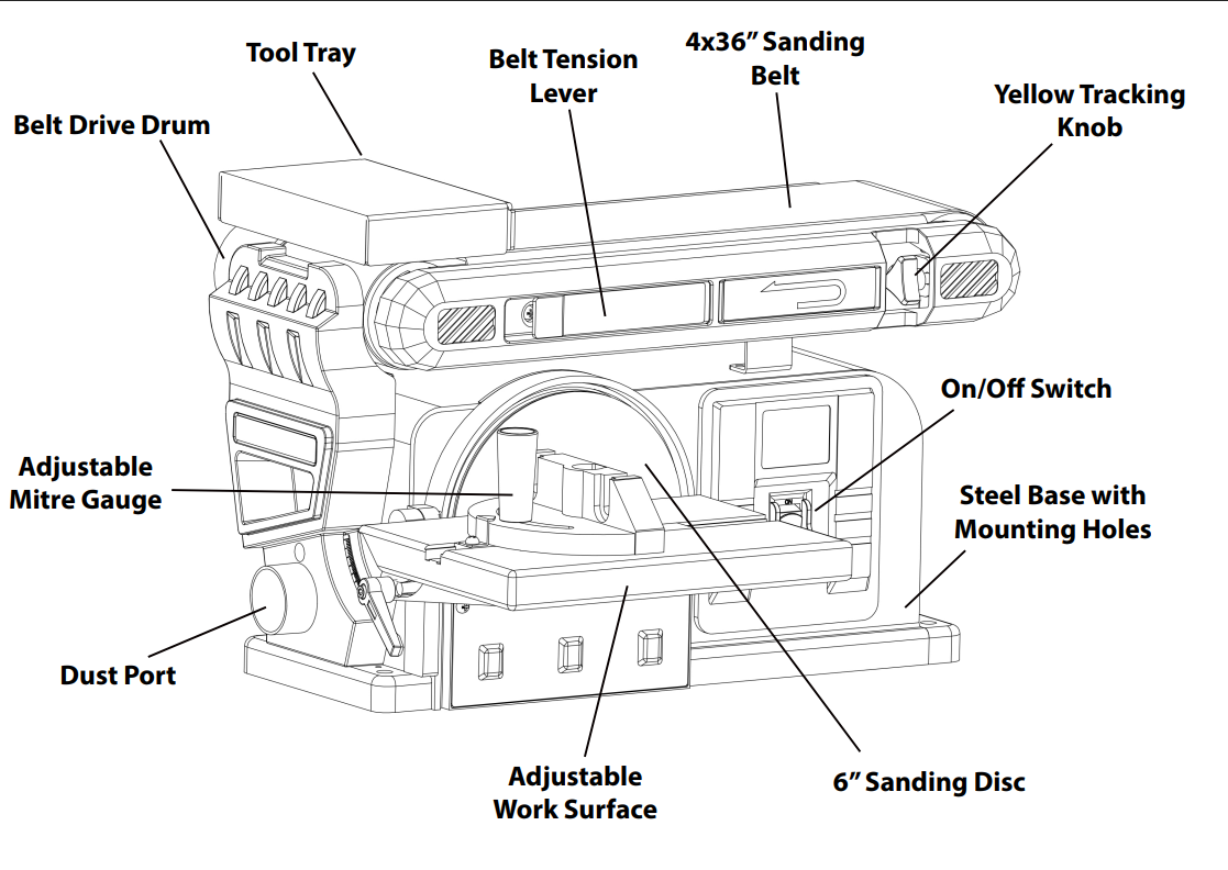
1x Part A - Disc/Belt Sanding Machine
1x Part B - Adjustable Work Surface
1x Part C - Mitre Gauge
1x Part D - Soft Grinder Attachment
1x Part E - Soft Grinder Head
1x Part F - 120 Grit Belt Sandpaper
1x Part G - 120 Grit Disc Sandpaper
2x Part H - 6mm Socket Head Screws and Washers
1x Part I - Tool Rest
1x Part J - 6mm Wrench
1x Part K - L-Pin

Monster Manual

Prepare the Machine

1. Secure to the Work Surface
NOTE: Ensure the machine is switched off and unplugged when making any adjustments to the machine
  • Using suitable nuts and bolts for your work surface (not included), securely bolt to your work surface at each corner of the machine. This ensures the machine doesn't move while in use.
2. Align the Belt Sand Paper
NOTE: Ensure the machine is switched off and unplugged when making any adjustments to the machine
  • Loosen belt tension by puling out the yellow Belt Tension Lever (located on the Belt Assembly above the Disc Sander) until it stops. It will remain in this position.
  • Centre the belt on the Belt Drive and the Idler Drums, sliding around the Belt Drive as needed.
  • Return the Belt Tension Lever to its place on the Belt Assembly.
  • Roll the belt by hand and check if the belt is skewing to one side, or making contact with the frame of the Belt Sander.
  • If skewing right, decrease the tension by turning the Yellow Tracking Knob up towards the work surface.
  • If skewing left, increase the tension by turning the Yellow Tracking Knob down away from the work surface
  • Repeat, if necessary, to ensure the Sanding Belt tracks evenly.
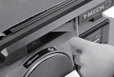
NOTE: With tool use, this will need to be adjusted occasionally.
Step 2 Image 1

Operating the Sander

1. Powering On
  • Plug the power cord into a 230V/50Hz outlet
  • Move the power switch into the "ON" position.
WARNING: Be careful not to touch the Sanding Disc and Sanding Belt as both will turn while the machine is on.
2. Using the Belt Sanding Feature
  • Allow your piece to rest gently against the Tool Rest and move it from side to side as the belt is moving.
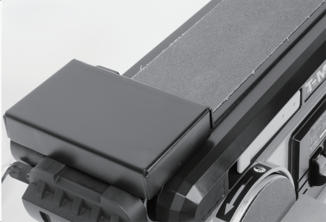
WARNING: Do not keep your workpiece in one place while sanding, and do not push your workpiece into the belt since this will overheat the belt, causing premature wear, failure and possibly personal injury. Be careful not to touch the Sanding Disc and Sanding Belt as both will turn while the machine is on.
Step 2 Image 1
3. Using the Disc Sanding Feature
  • Allow your piece to rest gently on the Adjustable Work Surface and gently press it against the disc as it rotates. Do not force into the disc.
  • Adjust the Adjustable Work Surface as required, vertically from 0° to 45°.
  • The Mitre Gauge is angle-adjustable horizontally through a full 120° to allow precise angle grinding.
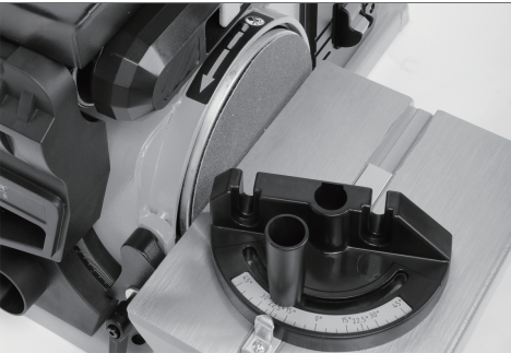
WARNING: Be careful not to touch the Sanding Disc and Sanding Belt as both will turn while the machine is on.
Step 3 Image 1
4. Using the Soft Grinder Attachment
NOTE: Ensure the machine is switched off and unplugged when making any adjustments to the machine
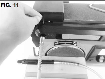
  • Remove the sticker on the cover, above the Sanding Disc to reveal the Soft Grinding Attachment hole.
  • Push the pin of the Soft Grinder Attachment into the hole.
  • Move the Sanding Belt by hand until the tightening nut is visible and lock it with the L-Pin.
  • Plug the machine in and move the switch into the "ON" position.
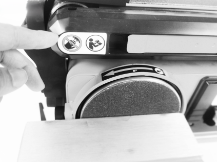
WARNING: Be careful not to touch the Sanding Disc and Sanding Belt as both will turn while the machine is on.
Step 4 Image 1
Step 4 Image 2

Optional Adjustments

1. Attaching the Tool Rest
NOTE: Ensure the machine is switched off and unplugged when making any adjustments to the machine
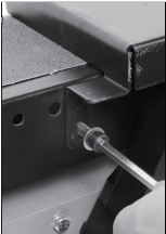
  • Place the Tool Rest (Part I) into position on top of the Sanding Belt and screw securely into place using the socket head cap screws and washers (Part H).
  • Ensure that there is no contact between the Tool Rest and the Sanding Belt. There should be approximately 1.5mm from the belt to the Tool Rest. Re-adjust if necessary.
Step 1 Image 1
2. Attaching the Adjustable Work Table
NOTE: Ensure the machine is switched off and unplugged when making any adjustments to the machine
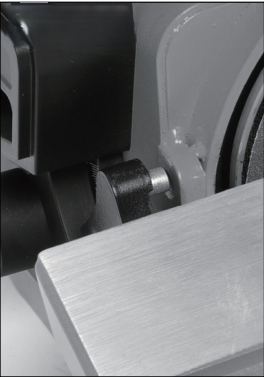
  • Place the locating pin into the hole of the Sanding Disc Protector Plate and secure with the Lock-Down Knob. Ensure the Work Surface is not in contact with the Sanding Disc. Re-adjust if necessary.
  • Slide the Mitre Gauge along the path in the Adjustable Work Surface, if desired.
Step 2 Image 1
3. Adjusting the Angle of the Sanding Belt
NOTE: Ensure the machine is switched off and unplugged when making any adjustments to the machine
  • The Belt Sander is adjustable from horizontal to 90° vertical.
  • To adjust, loosen the 6mm socket head cap screw on the Belt Sander Pivot Clamp with the 6mm Wrench (Part J).
  • Adjust the angle of the Sanding Belt to the desired work position.
  • Tighten the screw with the wrench securely to lock it in position.
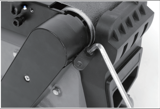
NOTE: Be certain the Belt Sander Assembly is securely clamped. Sever personal injury could occur if the Belt Sander Assembly position moves during use.
Step 3 Image 1
4. Replacing the Belt
NOTE: Ensure the machine is switched off and unplugged when making any adjustments to the machine. Always use a 4"x36" Sanding Belt, these are purchasable on Monster Shop.
  • Ensure the Belt Assembly is lifted from the horizontal position (See "Optional Adjustments: Step 3").
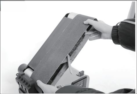
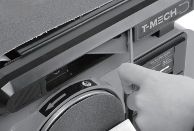
  • Loosen the belt tension by pulling out the Yellow Belt Tension Lever until it stops. It will remain in this position.
  • Pull the worn belt off the Belt Sander Assembly by pulling the belt towards you.
  • Place the new belt onto the Belt Sander Assembly by sliding over the Belt Drive
  • Snap the Belt Tension Lever back into place and following the steps from "Prepare the Machine: Step 2" to centre it
Step 4 Image 1
Step 4 Image 2
5. Replacing the Disc Sanding Paper
NOTE: Ensure the machine is switched off and unplugged when making any adjustments to the machine. Always use a 6" Hook and Eye Sanding Disc, these are purchasable on Monster Shop
  • Remove the Adjustable Work Table by loosening and removing the Yellow Locking Knob.
  • Peel away the worn Sanding Disc from the Backing Disc.
  • Clean any residue, grit or dirt from the Backing Disc.
  • Peel the backing paper off the new Sanding Disc, centre over the Backing Disc and press firmly into place. Ensure there are no bubbles or wrinkles.
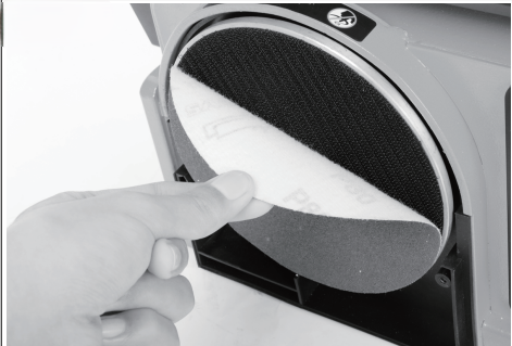
Step 5 Image 1
6. Switching the Soft Grinder Head
NOTE: Unplug the Soft Grinder Attachment from the machine when switching the Soft Grinder Head.
  • Rotate the Grinder Attachment Lock (on the tip of the Soft Grinder Attachment) until the internal pinhole lines up with the external pinhole on the handle.
  • Insert the L-Pin through the pinholes and twist the Grinder Attachment Lock to the right to unlock the Grinding Head. Replace the Grinding Head Tip and lock by twisting the Grinder Attachment Lock to the left.
  • The Soft Grinder is compatible with rotary burrs with a shank size of 3mm.
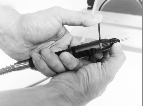
Step 6 Image 1

Exploded Diagram

Maintenance

Disconnect the machine from the mains before carrying out any maintenance. Regularly inspect and replace worn or damaged sanding belts and discs, tighten loose fasteners, keep the dust extraction port and ventilation openings clear, remove accumulated dust after each use, and periodically inspect the power cable, plug and guards for damage. Store the machine in a clean, dry environment when not in use.

Troubleshooting

Please read through the guide below if you have any issues or faults with your device. The information covers and resolves the majority of frequently asked questions.
Q: There are parts missing from my order.

A: If there appears to be any part missing from your package contact our Customer Support team via the details on the Contact page within 7 days of receipt.

Q: I have a technical/ spare parts query.
A: Contact our Customer Support team via the details on the Contact page.
For all other issues please contact our Customer Support department via the details on the Contact page.