This guide provides step-by-step instructions for assembling components and using a T-Mech Swing Gate Opener.
Product Information
T-Mech Swing Gate Opener
The Monster Heavy Duty Swing Gate Opener is an easily set up electromechanical gate opener that can be operated with 1st party or 3rd party controllers. Max single leaf 300kg and 2500mm.
SKU
26571
Input Power:
AC 110V/220V ± 10%
Motor Voltage:
24V DC
Power:
60W
Actuator Speed:
2.4 cm/s
Max. Actuator Travel:
300mm
Max. Single Leaf Weight:
300KGS
Max. Single Leaf Length:
3.6 meters
Ambient Temperature:
-22°C ~ +55°C
Protection Class:
IP55
Max Gate Opening Angel:
110°
GPSR Information
UK
Manufacturer:
Monster Group UK Limited, Monster House
19-23 Alan Farnaby Way,
Industrial Estate Sheriff Hutton,
York
YO60 6PG
Person Responsible:
Rana Harvey, Monster Group UK Limited,
Monster House
19-23 Alan Farnaby Way,
Industrial Estate Sheriff Hutton,
York
YO60 6PG,
England,
+441347878880
EU
Manufacturer:
Monster Group BV,
Van Heemskerckweg 28A & B,
Venlo 5928LL
Netherlands
+441347878880
Person Responsible:
Rana Harvey,
Monster Group BV,
Van Heemskerckweg 28A & B,
Venlo 5928LL,
Netherlands,
+44134787888
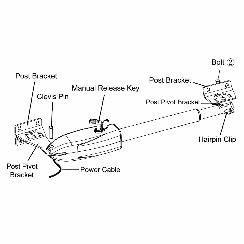
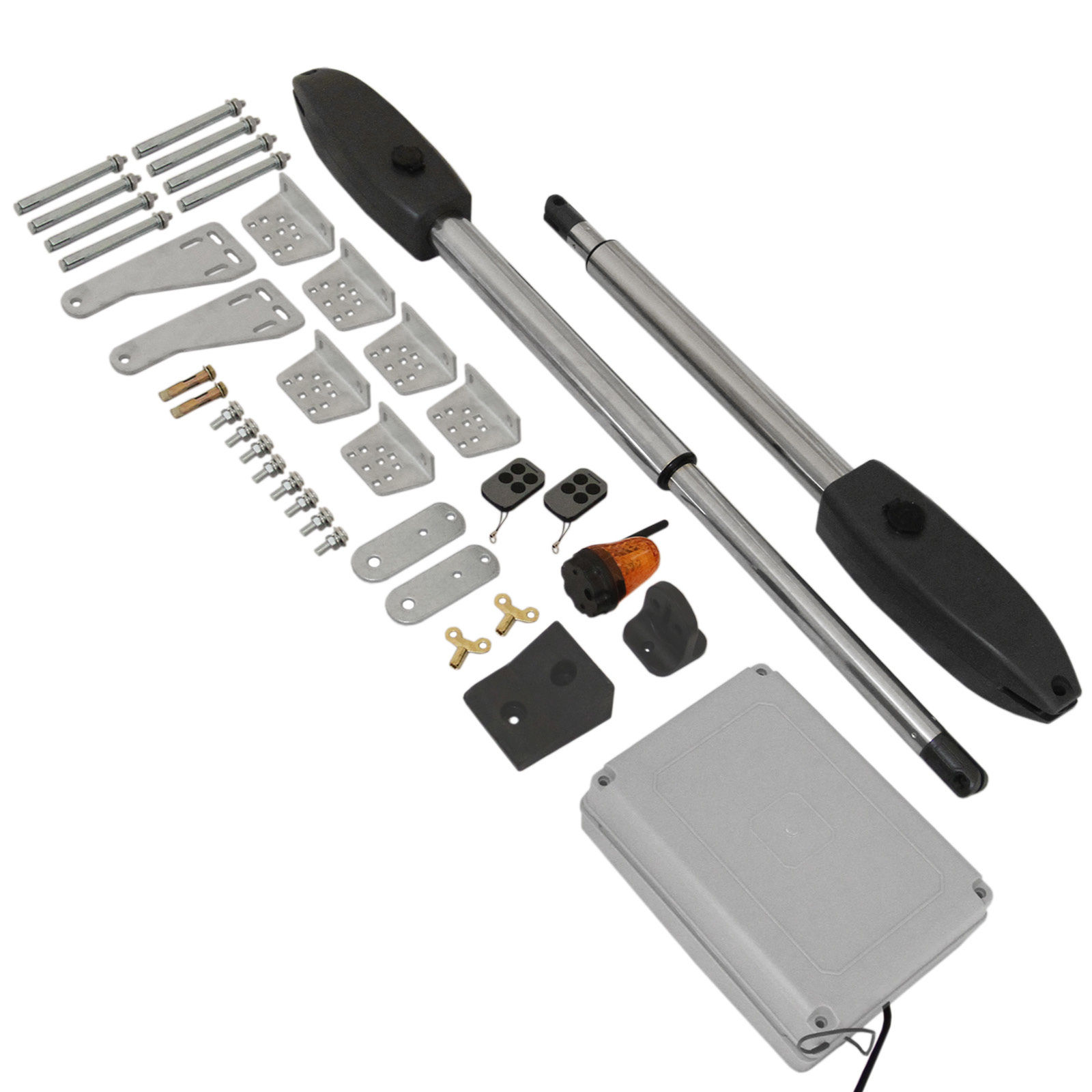
Parts
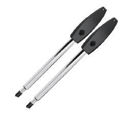
Gate Opener
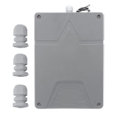
Control Box
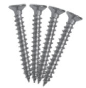
Control Box Screws Pack
Rubber Stopper
Rubber Stopper Screw
Remote Control
Manual Release Key
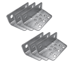
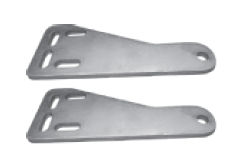
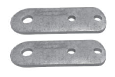
Post Bracket
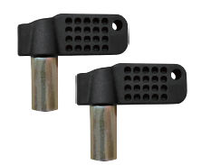
Post Pivot Bracket
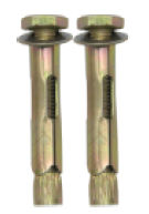
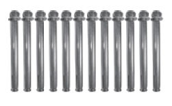
Bolts (1)
Bolts (2)
Clevis Pin
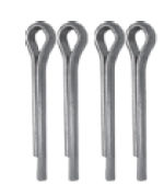
Hairpin Clip
Post Pivot Brackets
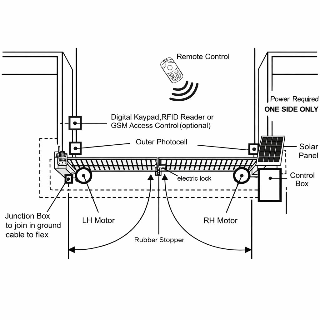
1. Installation Overview
2. Dual Gate Overview
IMPORTANT:
The gate opener cable should be put into the PVC conduit (not provided) which is buried
underground. This protects the cable from lawn mowers and string trimmers.
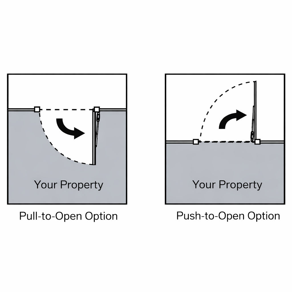
3. Installation Steps
There are two installation types for the gate opener, check for Proper Gate Installation & Direction of Gate.
NOTE:
Ensure the gate does not open into public areas.
4. Step 1 - Deciding the Height
Ensure that the post bracket height is in the same exact level with the gate bracket height. Failing to
ensure accurate common heights will cause the motor arm to bend leading to failure.
Also, the force to
push or pull the gate will be be reduced causing the motor to open or close the gates with difficulty or may
not operate successfully at all. Severe difference in height will damage the motor and the motor arm.
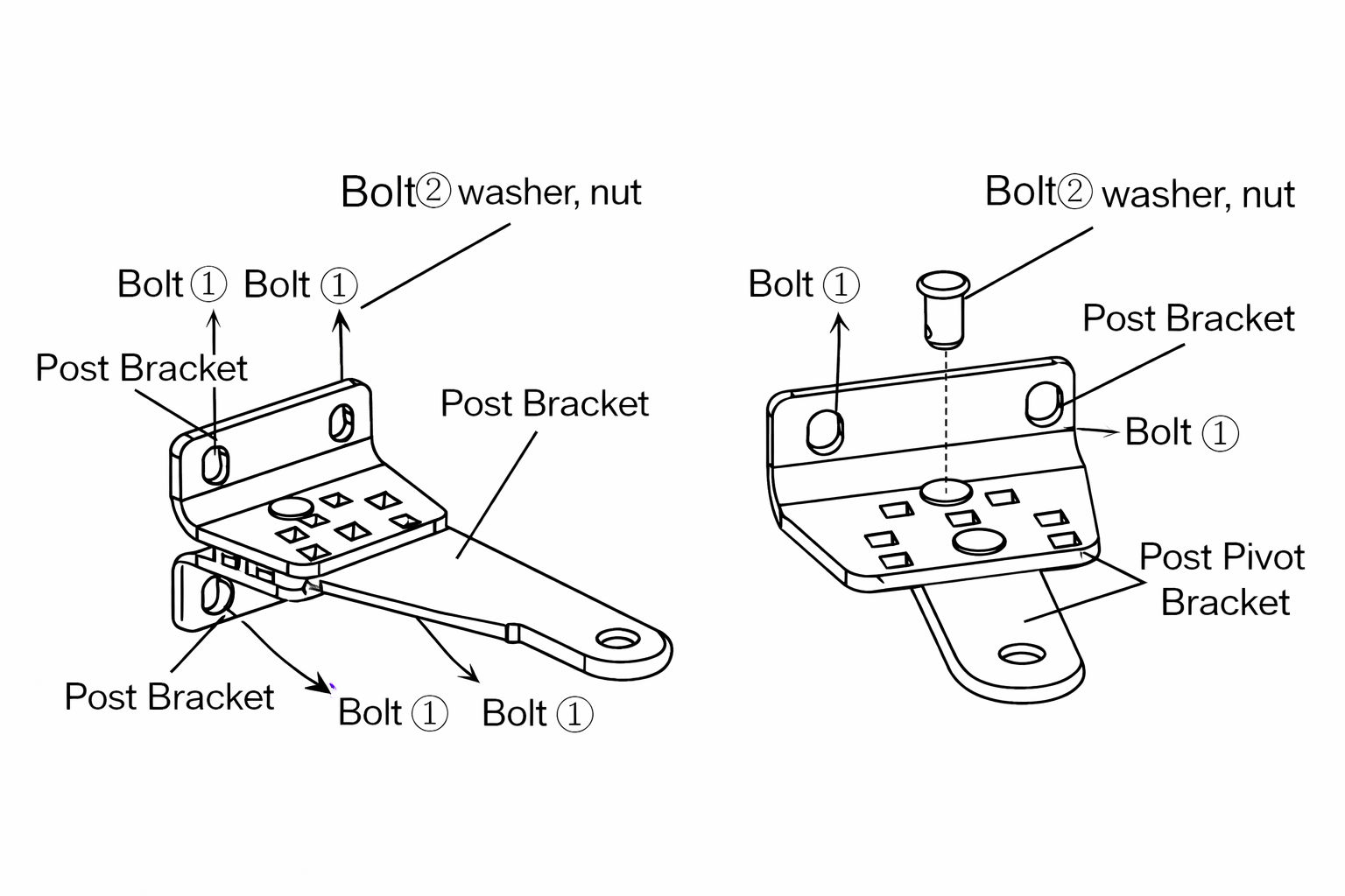
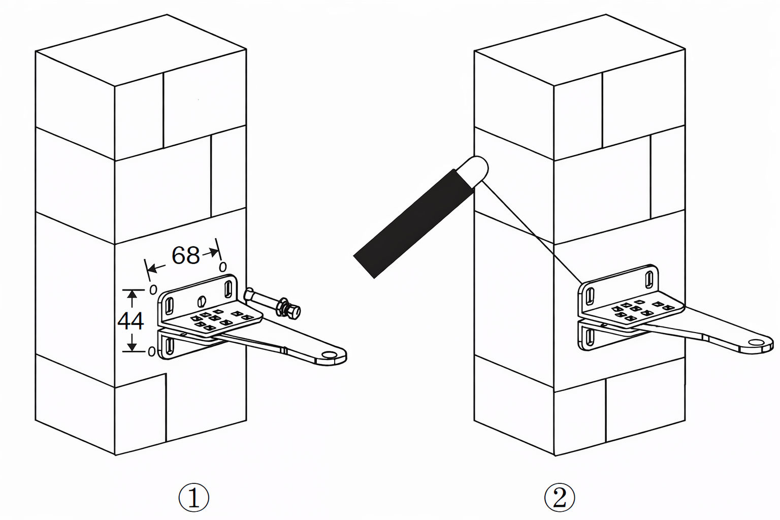
5. Step 2 - Post Bracket Installation
Insert the bolts (2) through the centre hole of the post bracket and post pivot bracket as shown.
Place the washer and nut on the bottom of the bolt and hand tighten.
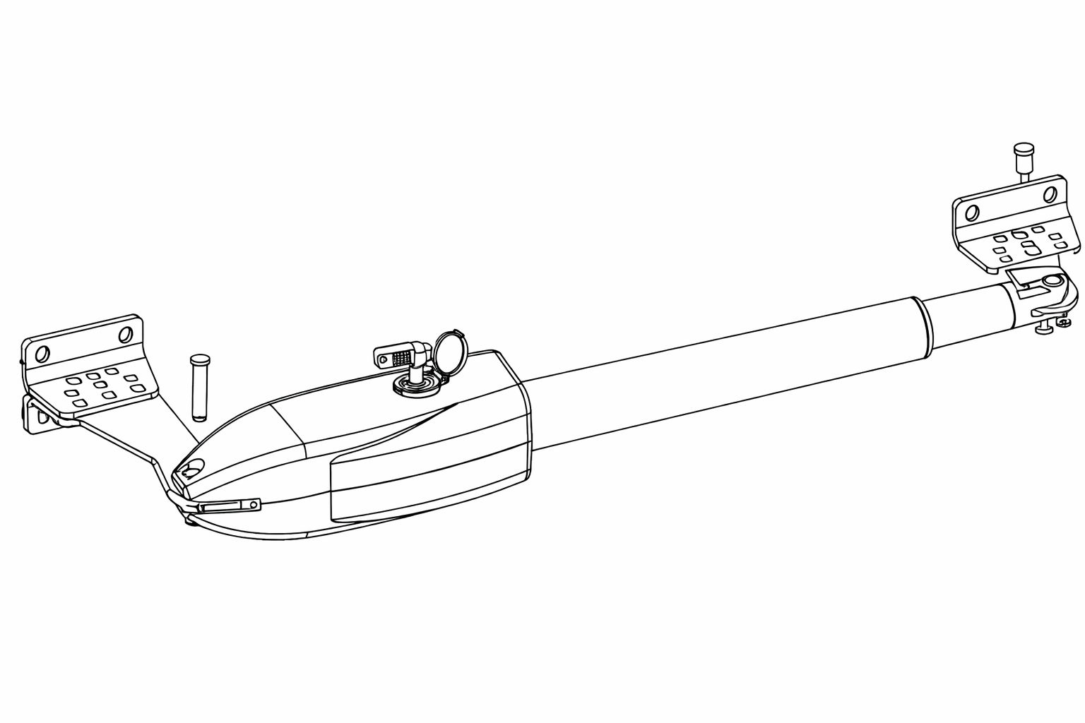
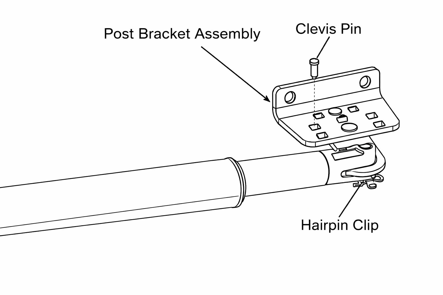
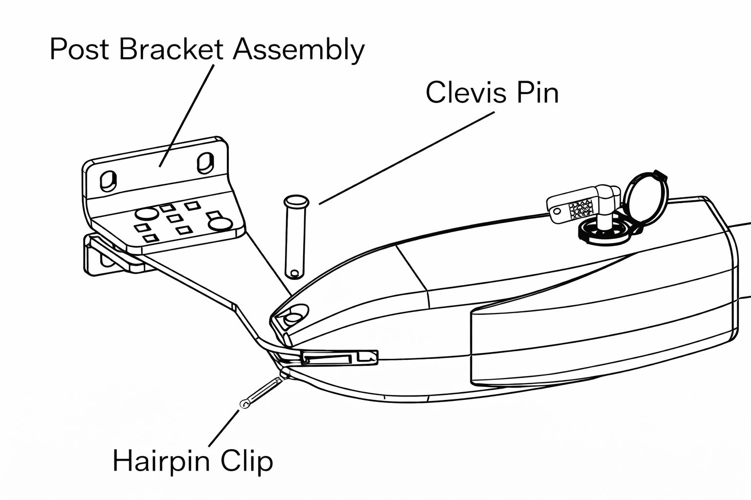
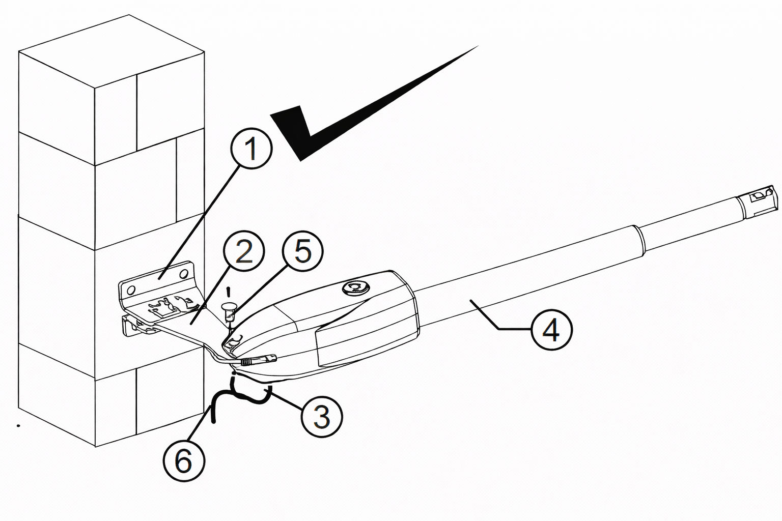
6. Step 3 -Install the Motor Fixed-End to the Gate Post-Bracket
Attach the gate bracket and the post bracket assembly to the opener by inserting a clevis pin.
Secure the clevis pins using the hairpin clips.
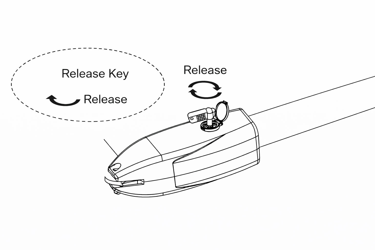
Open the release hole plug on the top of the gate opener, insert the release key, and turn the
key 90° clockwise. This releases the motor and allows the push-pull rod to be manually extended
and retracted. To restore normal operation, turn the key 90° counter clockwise.
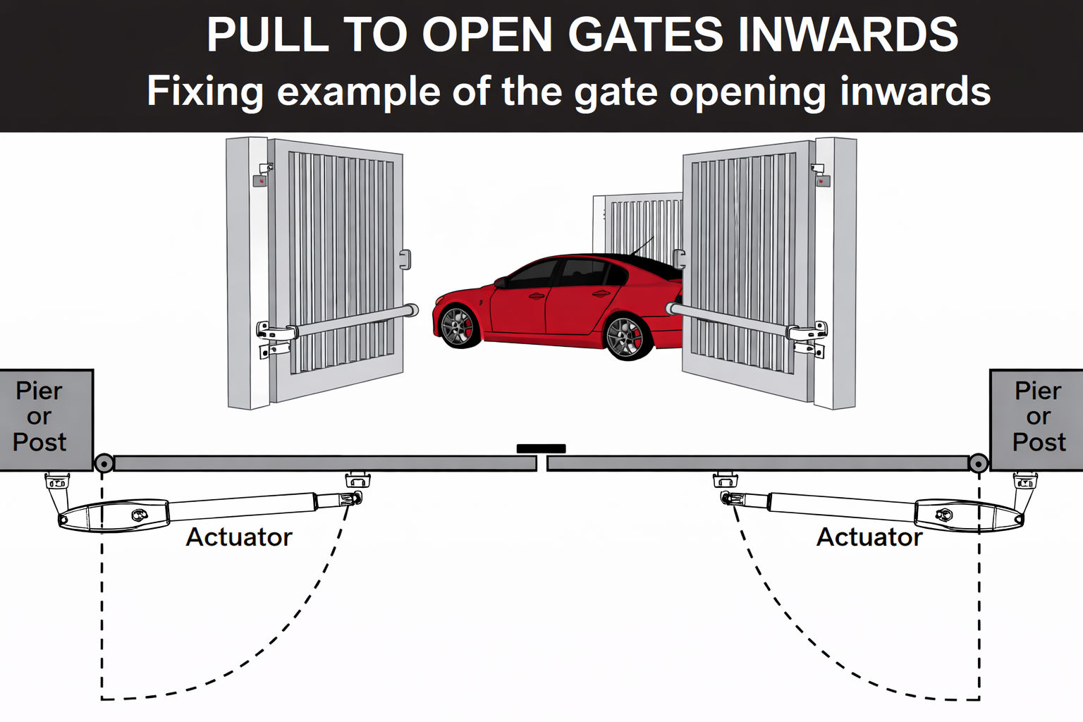
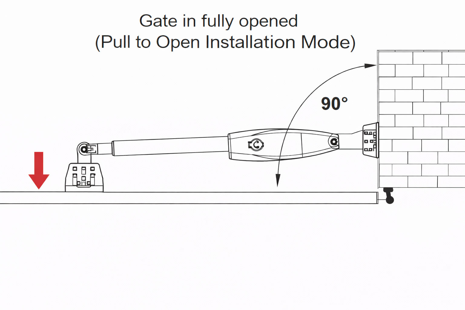
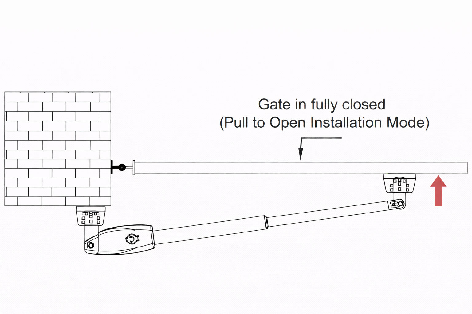
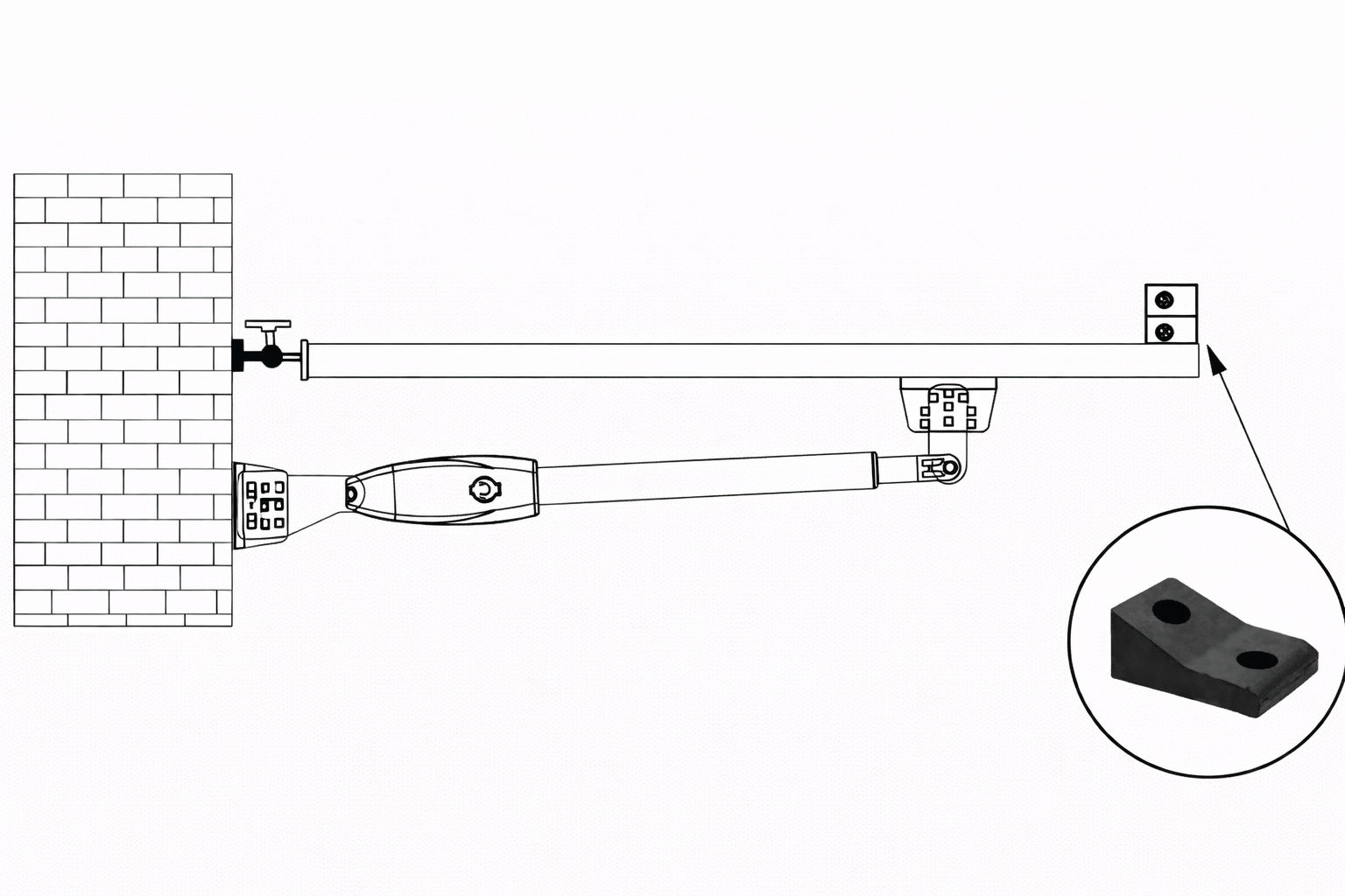
7. Step 4 - Pull-To-Open Installation Mode
IMPORTANT: There are two installation types for the gate opener, check for Proper Gate Installation & Direction of Gate.
Pull-To-Open Installation Mode:
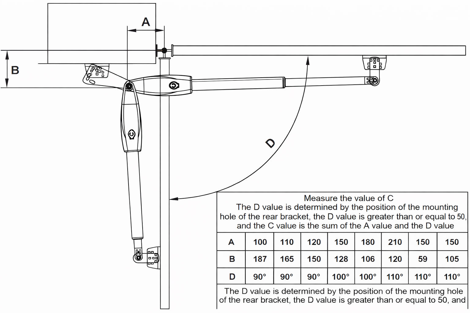
The installation position of the bracket is very important. Please refer to the figure to measure according
to the angle you need to open. Unit: mm (for example: A is 150mm, B is 105mm. At this time,
the maximum opening angle of the gate is 110°), determine the centre point of the shaft and mark it.
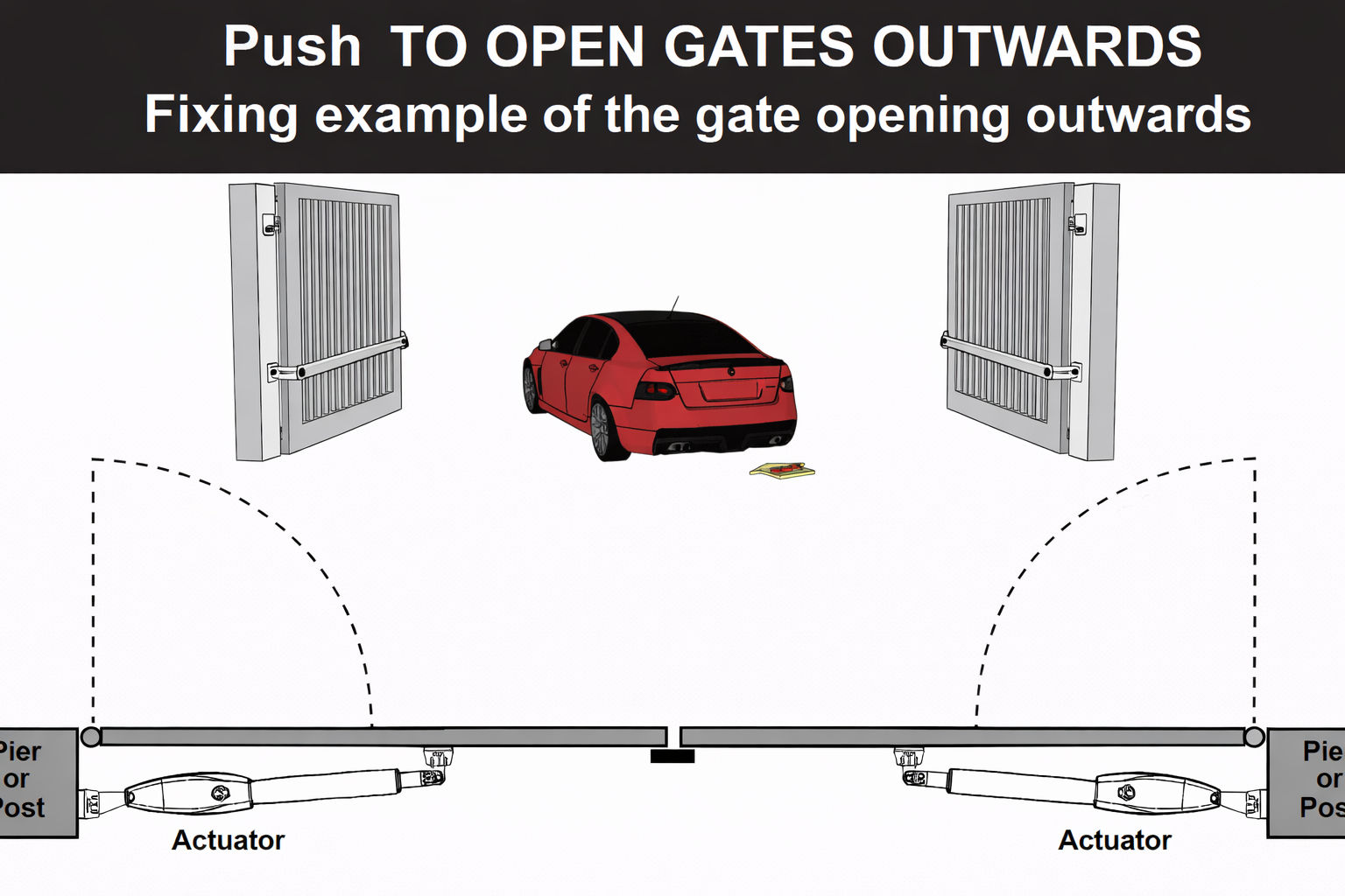
8. Step 4 - Push to Open Installation Mode
IMPORTANT: There are two installation types for the gate opener, check for Proper Gate Installation & Direction of Gate.
Push to Open Installation Mode:
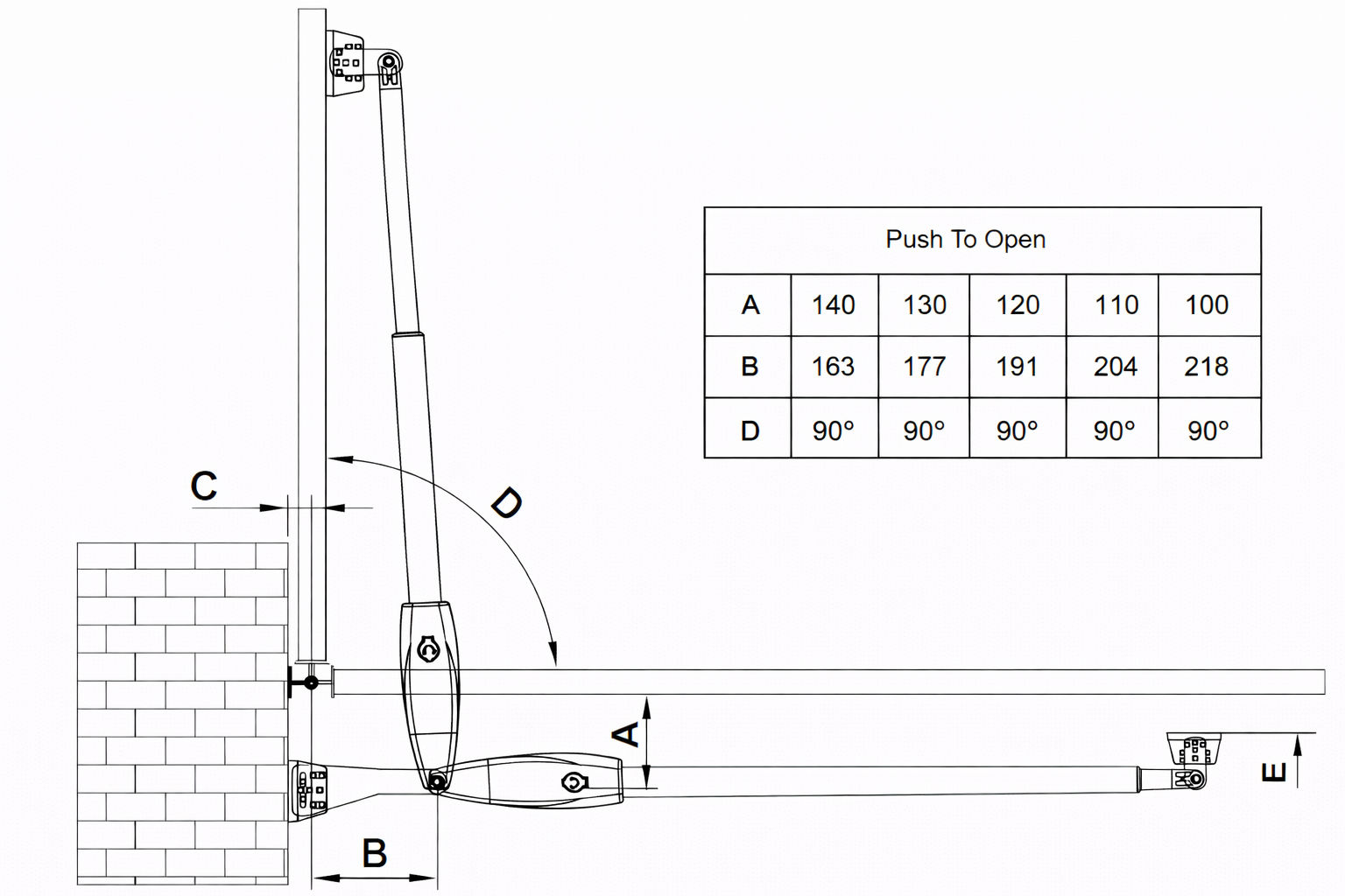
The installation position of the bracket is very important. Please refer to the figure to measure according
to the angle you need to open.
Determine the centre point of the shaft and mark it.
1. The post bracket plate is attached to the fixed bracket with an appropriate angle. Take out the gate opener arm to install the gate brackets and post brackets on to the gate machine (the bracket angle is adjustable). 2. Fully open the gate (take 90° as an example) and retract the arm of the gate opener to the shortest position (when determining the position of the gate bracket on the gate, make the gate and the wall where the rear bracket is vertical). The post bracket is close to the wall, and the gate bracket is close to the gate body. Mark the position on the gate body with a marker. 3. Fully close the gate to 180°, extend the arm of the gate opener to the longest, place the gate bracket on the market point on the previous gate, and observe whether the position is correct, drill holes at the marked position on the gate body to mount the bracket. Then the gate machine is placed horizontally, the position of the bracket is determined, and the hole is drilled. Hit the expansion screw to mount the brackets.
NOTE:
Moving the bracket up will make the doors opening angle bigger.
Moving the bracket to the left will make the doors closing angle smaller.
Moving the bracket to the right will make the doors closing angle bigger.
Moving the bracket down will make the doors opening angle smaller.
It is recommended to open and close the gate back and forth by switching between the longest
and shortest position of the gate opener’s arm. Determine that the marked point is correct,
and then insert perforated lock screws or weld to mount the brackets.
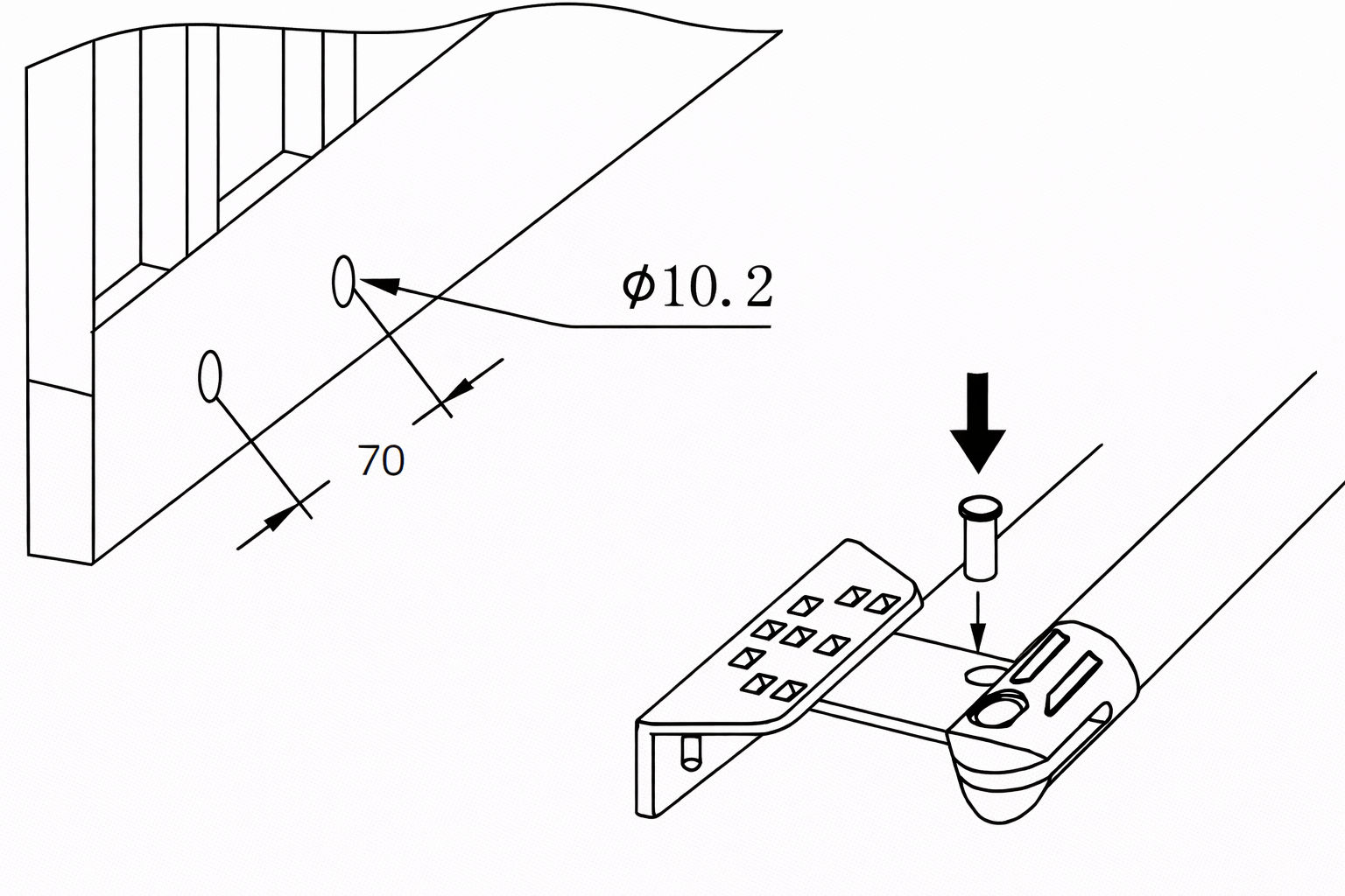
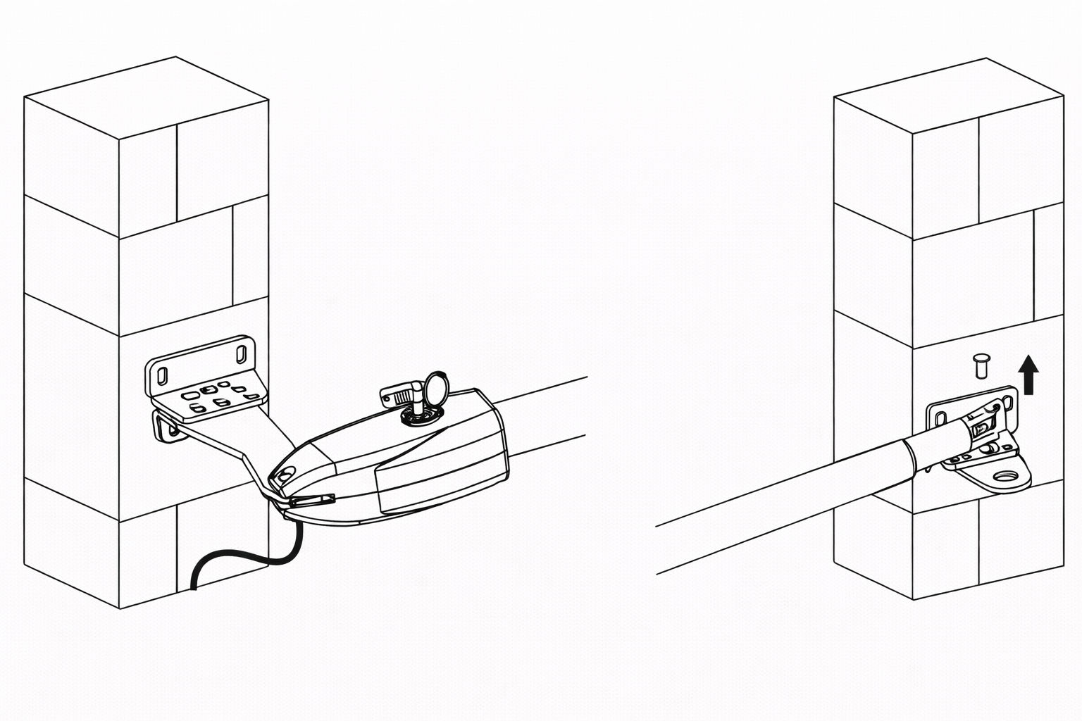
9. Step 5 - Hole Installation / Welding
1. Fix the post bracket to the wall:
Construction Drill and Bolts: Drill 4 Holes of 8mm Diameter. Insert the 4 Provided Concrete Bolts (1) and Tighten Properly (Do not over tighten as you may strip the bolt out of the concrete or the brick). Place the Motor Connecting Bracket and Tig. Construction Drill and Weld: Drill 4 Holes of 8mm Diameter. Locate the 4 Slotted Holes Post Bracket above the Drilled Holes. Weld the Motor Bracket to the Post Bracket. 2. Adjusting the angle of the motor drainage hole:
See the second image. The cable must not be installed above the motor arm. It may pinch and strip the cable and causes electric shock. * The manual override release must be located face to the view of the public. 3. Attach the rear bracket to the gate body:
Drill 2 Holes of 10.2mm diameter with a space of 70mm between the 2 holes. Locate the 2 slotted holes gate bracket above the drilled holes. Place the end motor bracket to the gate bracket using the appropriate bolts and tighten properly. Please note that the bolts used to fix the front bracket to the gate are not provided, due to the thickness of each gate being different. Insert the lock pin and clamping washers.
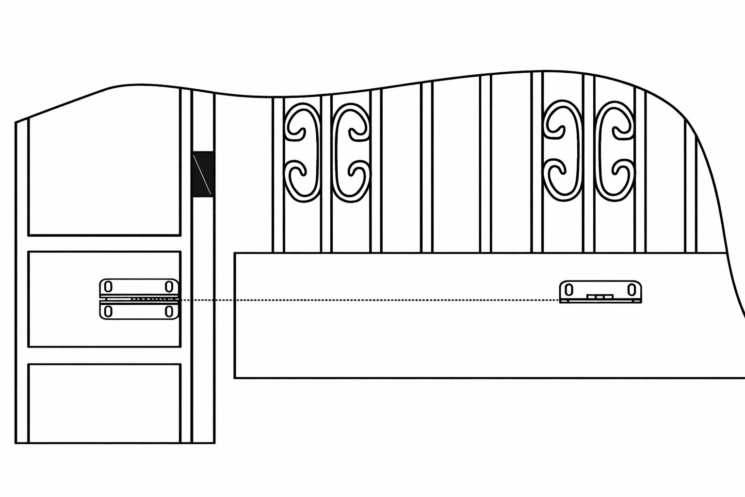
10. Step 6 - Installing the Gate Rubber Stopper
Install the gate rubber stopper.
11. Step 7 - Emergency Release Function
The schematic diagram of opening the gate body when there is no power is shown above. Please use the
emergency release key to loosen the gate bracket and the arm of the gate opener. Then lift it up.
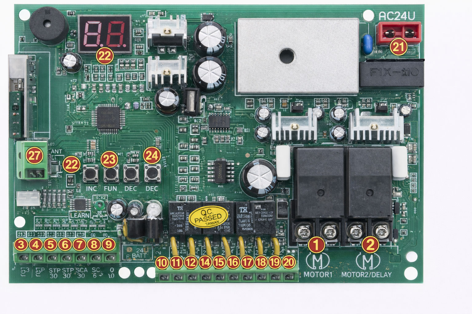
12. Control Board Instructions
Power Supply: AC 24V , available for adding 24V backup battery.
Application: Used for double or single DC 24V swing gate opener.
Encoder For transmitter: Factory owns rolling code.
Allowed Transmitters Quantity: Up to 120PCS.
MOTOR 1: Slave gate, close first & open last. This terminal connect 1st blue wire (counted from your
left hand side to right hand side)
MOTOR 2 (DELAY) : Master gate, open first & close last. This terminal connect 1st red wire (counted
from your left hand side to right hand side).
NOTE! If you only have a single gate, the motor only can connect to the Motor 2 Delay terminal.
2 SIDE: For connecting to any external device that operates a double gate.
COM: For connecting to the “ground”.
1 SIDE: For connecting to any external device that operates the single gate.
Swipe Card: For connecting to any external devices that will operate to open the gate.
COM: For connecting to the “ground” external device.
IR: Infrared terminal is for connecting to the safety beam.
12V: The output is for connecting to the photocell sensor, continuous output current <=200mA.
(24V DC output, current is 1A).
24V battery +: For connecting the backup battery +.
24V battery -: For connecting the backup battery -.
24V: 24V DC output is for connecting to an external device.
GND: For connecting to the ground of an external device.
24V Lamp +: For connecting to the flash light +.
24V Lamp -: For connecting to the flash light -.
Lock (NF): The NF terminal which is used for connecting to the electric lock.
Com(24V): Common used for connecting to the ground of the lock.
Lock(NA): The NA terminal which is used for connecting to the magnetic lock.
GND: For connecting to the ground of the alarm system.
SP: 24V DC output connecting with the alarm system.
AC 24V: For connecting with the transformer.
Digital display: For showing you the setting data.
INC+: For figure increasing
FUN: Used for enter the menu setting and confirm the data.
DEC-: For figure decreasing of setting the data.
Learning button: For programming / erasing the remote control.
ANT and GND: Used for connecting with the antenna.
13. Troubleshooting
Please read through the guide below if you have any issues or faults with your device. The information covers and resolves the majority of frequently asked questions.
Q: There are parts missing from my order. A: If there appears to be any part missing from your package contact our Customer Support team via the details on the Contact Us page within 7 days of receipt.
For all other issues please contact our Customer Support department via the details on the Contact page.